Rockwell Automation 8520 9/Series CNC Lathe User Manual
Page 86
Offset Tables and Setup
Chapter 3
3-18
offset data on the current page. Press the
{MORE OFFSET}
softkey to
change pages. The selected item appears in reverse video.
4.
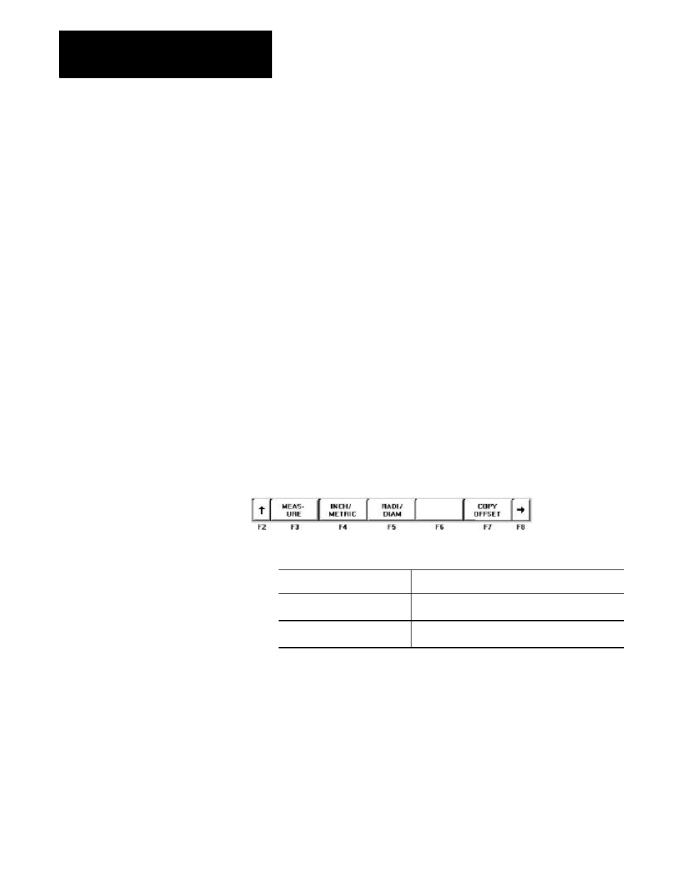
Select data entry type:
Unit selection {INCH/METRIC}
To select units of “mm” or “inch” for the offset data, press the
{INCH/METRIC}
softkey. The units used for the currently selected
offset G-code or external offset change each time the softkey is
pressed. When the units are altered, all data previously entered is
converted to the newly selected units for that offset number.
Diameter or Radius {RADI/DIAM}
If the offset value being changed has been selected in AMP as the
diameter axis (typically the axis perpendicular to the spindle center
line), data may be entered into the offset table as either a radius or
diameter value. The current mode for this axis is displayed with an R
for radius or a D for diameter mode next to that axes offset. Pressing
the
{RADI/ DIAM}
softkey toggles the offset between these two
modes.
This softkey does not change the current mode of control operation
(as selected with G07 or G08); it only alters how data is entered into
the table. For details, refer to chapter 13 (G07/G08).
(softkey level 3)
5.
Replace or add data as follows:
To :
Press:
replace stored work coordinate
data with new data
the {REPLCE VALUE} softkey, then type in the
value and press [ENTER].
add to previously stored work
coordinate data
the {ADD TO VALUE} softkey, then type the
number and press [ENTER].
Important: The values for the work coordinate systems can be altered
by using the G10 command in MDI or within a part
program. For details, refer to chapter 11.