Rockwell Automation 8520 9/Series CNC Lathe User Manual
Page 363
Axis Motion
Chapter 14
14-5
You must establish a plane before the control performs the correct arc.
This should have been done by your system installer, typically assigning
the Z and X axes to the G18 plane. This becomes the default plane that the
control assumes when:
power is turned on
E-Stop is reset
the control is reset
Circular interpolation can be performed in the absolute (G90) or
incremental (G91) mode.
Important: S--Curve Acc/Dec mode is not available with circular
interpolation mode.
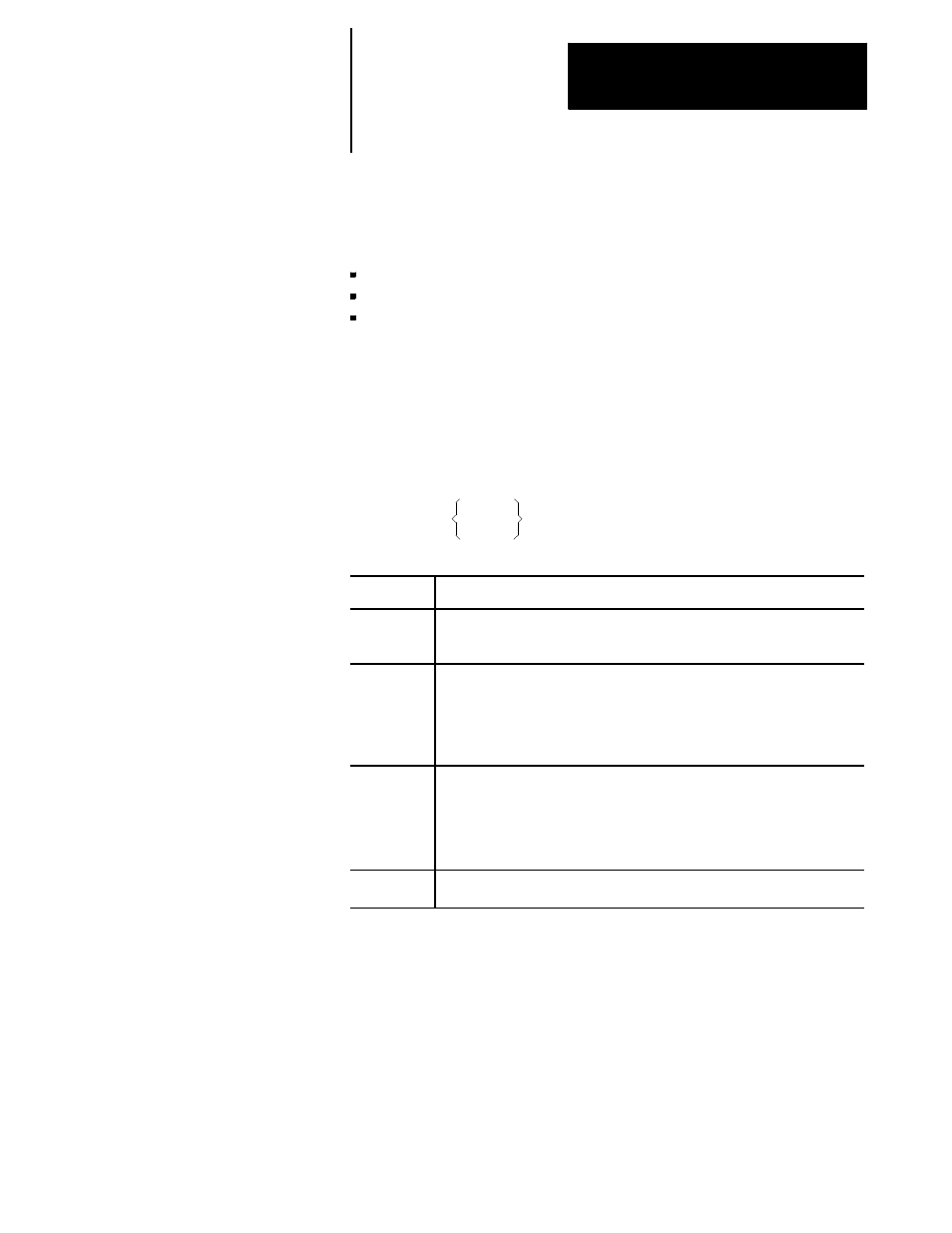
The format for circular interpolation in the ZX plane is:
{G02} X__ Z__
I__ K__
F__ ;
G03
R__
Where :
Is :
X, Z
In absolute (G90) mode, these are the work coordinate values of the end point.
In incremental (G91) mode, these are the positions of the end point in reference
to the start point.
I, K
These determine the position of the arc center. They are the incremental
distance on each axis from the start point of the arc to the center point. These
values are always incremental, regardless of the established positioning mode
(absolute or incremental). I is parallel to X axis, and K is parallel to Z axis;, but
his can be configured in AMP. These are not necessary if programming the R
parameter.
R
Rather than defining a center with I, K, the option exists to define an arc radius
using R. The sign of this entry determines the arc centerpoint location. If R is
programmed as a positive value, the centerpoint is located so that an arc less
than 180
°
is generated. If R is programmed as a negative value, the centerpoint
is located so that an arc greater than 180
°
is generated. Refer to Figure 14.5 for
an example.
F
Another option is to enter a feedrate tangential to the arc. If omitted, the control
uses the feedrate active prior to this block.