Rockwell Automation 8520 9/Series CNC Lathe User Manual
Page 697
Paramacros
Chapter 28
28-23
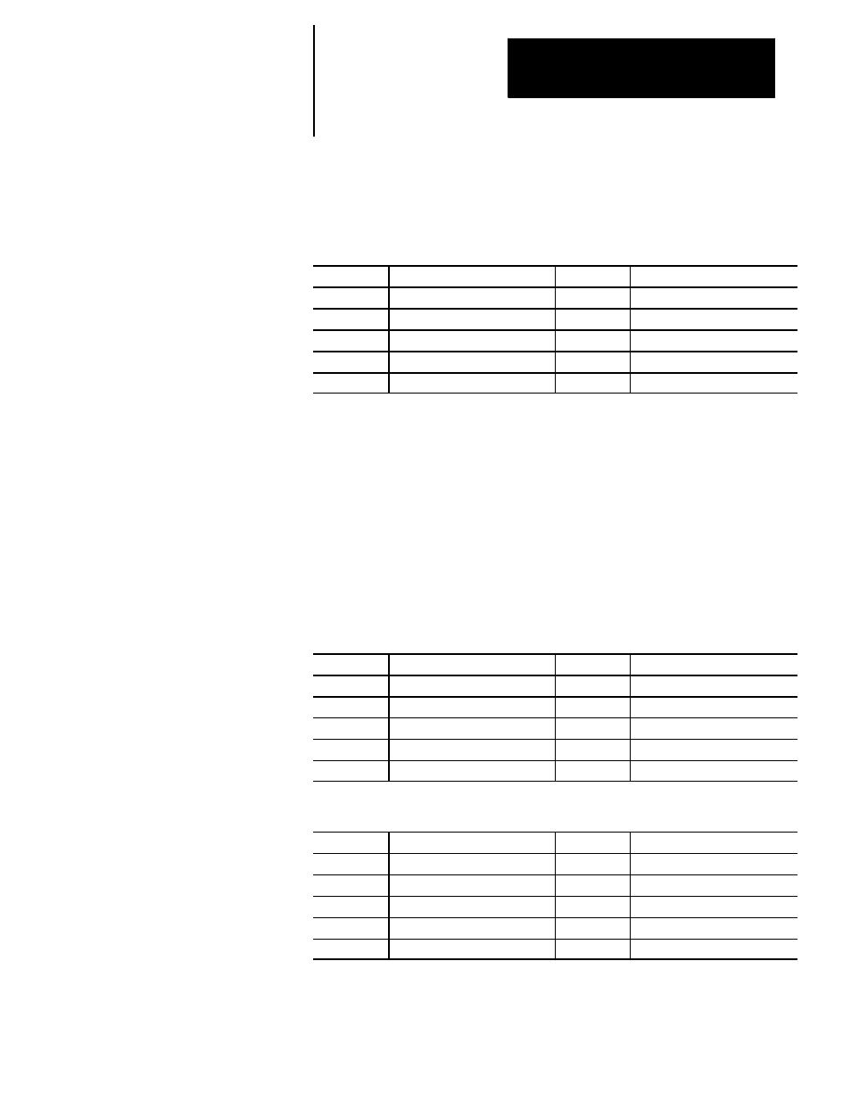
#5041 to 5052
Machine Coordinate Position
These parameters are read-only. They correspond to the coordinates of the
cutting tool in the machine (absolute) coordinate system.
5041
Axis 1 coordinate position
5047
Axis 7 coordinate position
5042
Axis 2 coordinate position
5048
Axis 8 coordinate position
5043
Axis 3 coordinate position
5049
Axis 9 coordinate position
5044
Axis 4 coordinate position
5050
Axis 10 coordinate position
5045
Axis 5 coordinate position
5051
Axis 11 coordinate position
5046
Axis 6 coordinate position
5052
Axis 12 coordinate position
The system installer determines in AMP the name (or word) that is used to
define the axis.
Position data for the absolute position of an adaptive depth probe is
invalid.
#5061 to 5069 or #5541 to 5552
Skip Signal Position Work Coordinate Position
These parameters are read-only. They correspond to the coordinates of the
cutting tool when a skip signal is received to PAL from a probe or other device
such as a switch. These are the coordinates in the work coordinate system.
5061
Axis 1 coordinate position
5067
Axis 7 coordinate position
5062
Axis 2 coordinate position
5068
Axis 8 coordinate position
5063
Axis 3 coordinate position
5069
Axis 9 coordinate position
5064
Axis 4 coordinate position
5065
Axis 5 coordinate position
5066
Axis 6 coordinate position
Or if your system has more than 9 axes:
5541
Axis 1 coordinate position
5547
Axis 7 coordinate position
5542
Axis 2 coordinate position
5548
Axis 8 coordinate position
5543
Axis 3 coordinate position
5549
Axis 9 coordinate position
5544
Axis 4 coordinate position
5550
Axis 10 coordinate position
5545
Axis 5 coordinate position
5551
Axis 11 coordinate position
5546
Axis 6 coordinate position
5552
Axis 12 coordinate position
The system installer determines in AMP the name (or word) that is used to
define the axis.