1 measuring interference boundaries – Rockwell Automation 8520 9/Series CNC Lathe User Manual
Page 762
Chapter 30
Using a 9/Series Dual--Processing System
30-22
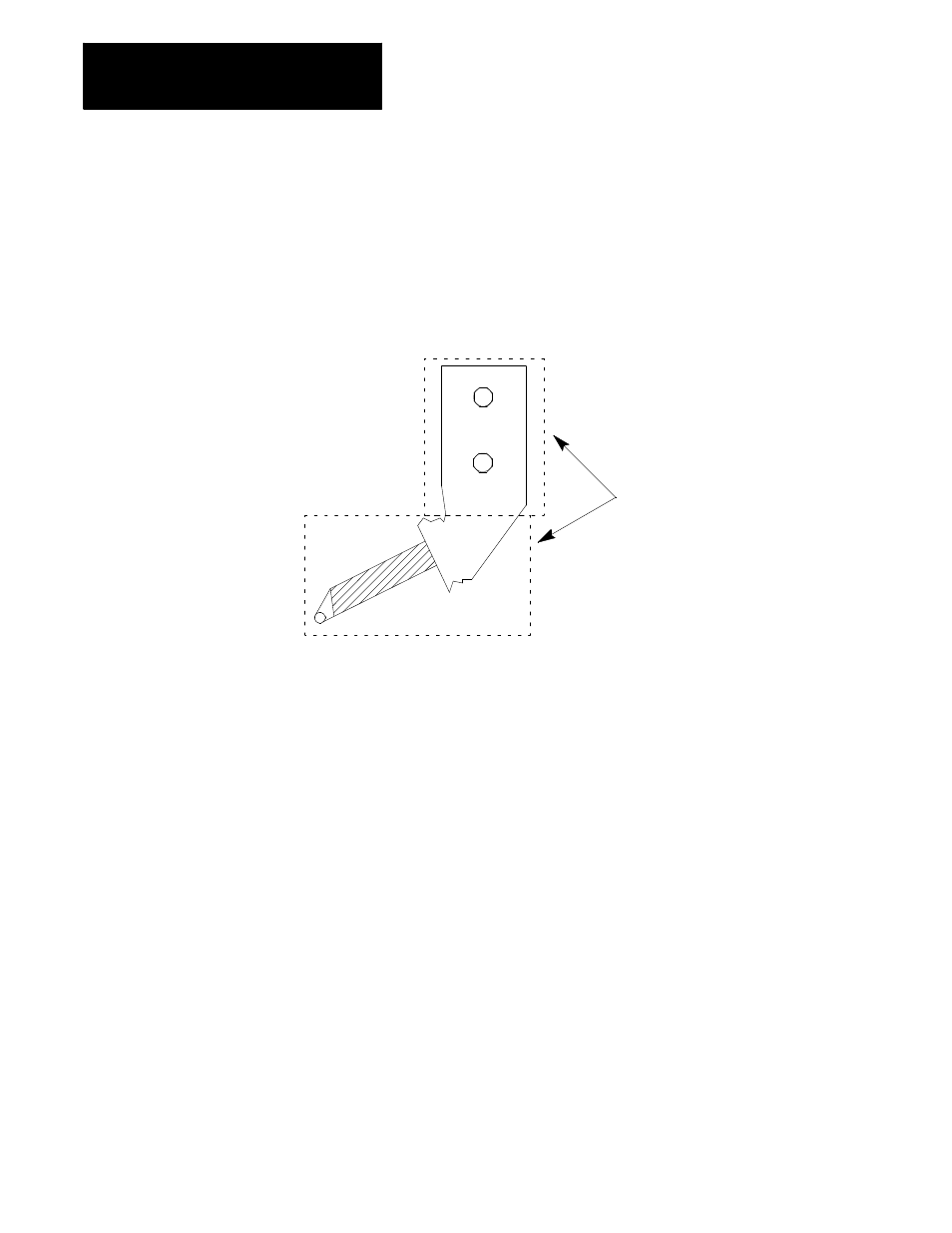
The control can store as many as 32 different boundaries for each process.
Two separate areas make up each of these boundaries. Both axes are
activated when the boundary is activated through PAL. Figure 30.10
illustrates the use of two areas to make up interference boundary 01.
Figure 30.10
Using Two Areas to Define an Interference Checking Boundary
Area 1
Area 2
These areas define an interference boundary.
A maximum of 32 boundaries can be defined
containing 64 actual areas (two areas in each
boundary).
12605-I
At least one area must be defined for a boundary to be considered valid for
activation. If only one area is defined, the control assumes the second area
does not exist.
Areas for interference checking are defined in the machine coordinate
system for the fixtures positions as the axis sits at the home position.
Only two axes can be entered into the interference tables to define a
boundary. Your system installer selects these two axes in AMP. Follow
this procedure to measure values defining your interference areas:
1.
Return the axes to the home position (with no offsets active). This
can be accomplished by manually homing the machine (see chapter
4) or by programing a G28 (see chapter 14).
2.
Measure the values defining the interference area for each axis as
shown in Figure 30.11.
You will probably need to take different measurements for all of the
different fixtures and tools you will be using. Regardless of the tool
or fixture being used, the machine must remain at machine home
(with no offsets active) when the measurements are taken.
Interference areas are always measured as radius values. Data cannot
be entered into the interference tables as diameter values.
30.5.1
Measuring Interference
Boundaries