1 tool dimensional parameters – Rockwell Automation 8520 9/Series CNC Lathe User Manual
Page 71
Offset Table and Setup
Chapter 3
3-3
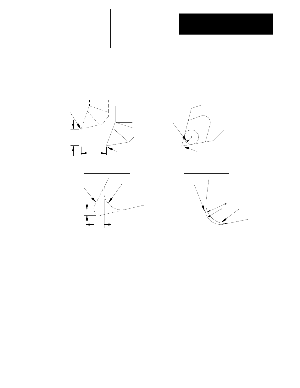
Figure 3.2
Tool Dimensional Offsets
Worn cutting
edge
R’
R
Cutting edge before
tool wear
Worn cutting
edge
Cutting edge before
tool wear
Z
X/2
Z
X
R = R’- R
Actual tool
position
Assumed tool
position
Actual tool
tip point
R
TOOL WEAR, RADIUS
TOOL WEAR, LENGTH
TOOL GEOMETRY, LENGTH
TOOL GEOMETRY, TIP RADIUS
Assumed tool
tip point
Tool Length (Tool Geometry Table)
The dimensions, entered into the tool geometry for length, reflect the
distance from the tool tip to the gauge point on the tool holder. This gauge
point actually moves to the coordinates programmed in a part program, if a
tool offset is not activated.
We use the term “gauge point” to define the precise point on the turret
from which all programmed tool paths originate. Offsets refer to the
distance from this gauge point to the tip or edge of the tool that contacts
the part being cut.
Use the tool length offset function to compensate for the difference
between the tool position as mounted in the turret and the tool position
assumed in writing a program. By using the tool length offset functions
along with tool orientation data, a programmer can write a part program
without further concern for tool position due to mounting. Measure offset
values for each axis to allow for the difference between the assumed and
actual cutting tool locations.
3.1.1
Tool Dimensional
Parameters