Rockwell Automation 8520 9/Series CNC Lathe User Manual
Page 570
Compounding Turning Routines
Chapter 24
24-6
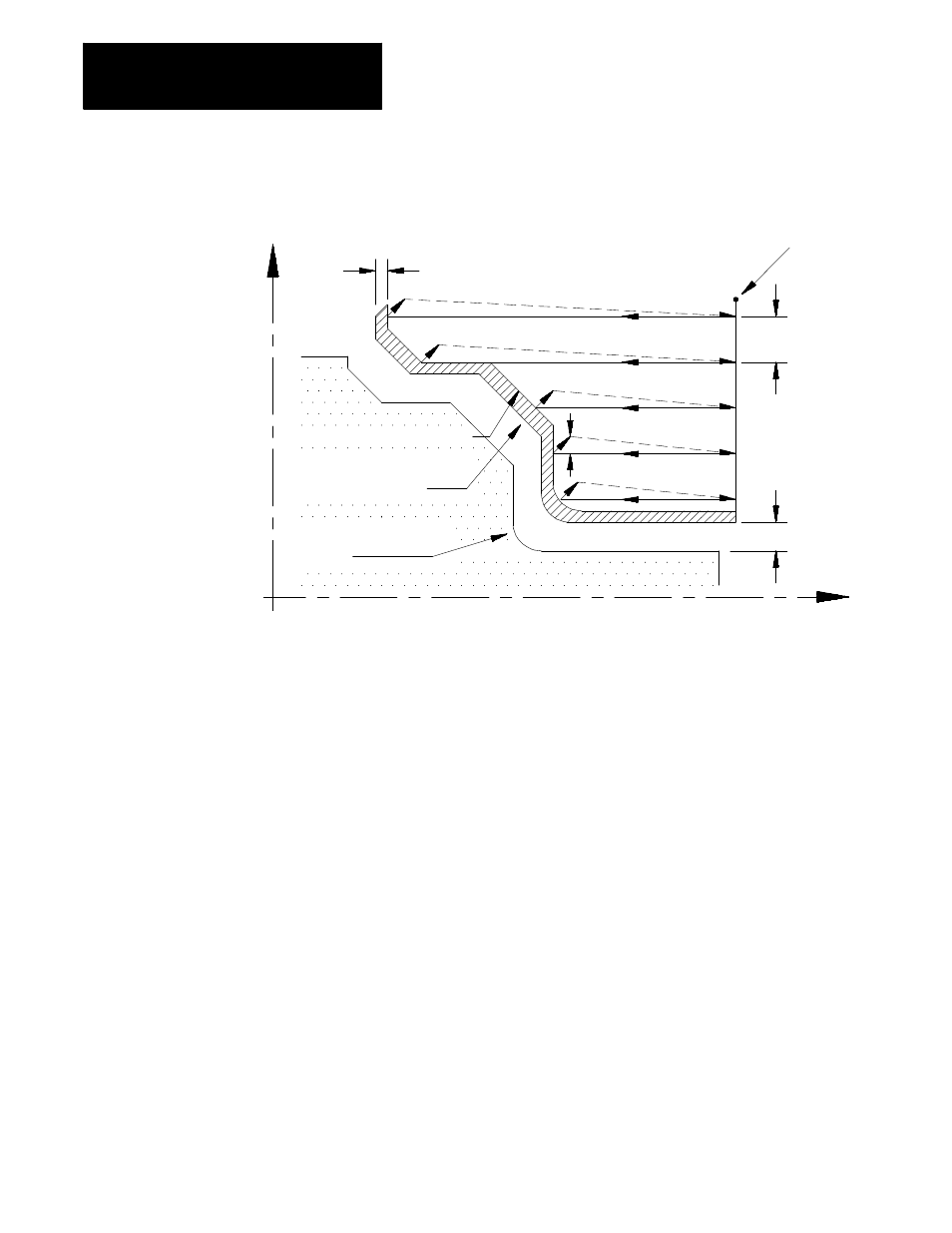
Figure 24.3
Parameters for G73 Roughing Routine
Shape after roughing
Shape after roughing
and final pass
Workpiece finished
shape
Start Point
D
(U+W)/2
Z
X
R
(I+K)/2
In Figure 24.3, the contour blocks for this routine must define all motions
that would cut the workpiece finished shape. The first block of the contour
blocks must be the tool path from the start point to the point where the
initial roughing pass begins (point A to B in Figure 24.3).
The contour blocks can be programmed with or without a feedrate, or with
a G00 (rapid) command The control uses the feedrate specified by the
F-word in the G73 block during all roughing portions of the routine.
During the final contour pass of the roughing cycle, the control executes
your feedrate programmed in your contour block (unless you do not use
one, then it uses the F-word in the G73 block). This final contour can even
contain rapid moves (G00).
Important: The blocks preceding the G73 roughing block must have
positioned the cutting tool to a location above the part (start point in the
above figure) from which it can safely move to begin the roughing passes.
If cutting a Case 1 contour, the first of the contour blocks must command
X axis motion only (no Z axis motion). If cutting a Case 2 contour, the
first of the contour blocks must command both an X and Z axis motion.