3 corner movement after generated blocks – Rockwell Automation 8520 9/Series CNC Lathe User Manual
Page 525
Tool Tip Radius Compensation (TTRC)
Function
Chapter 21
21-41
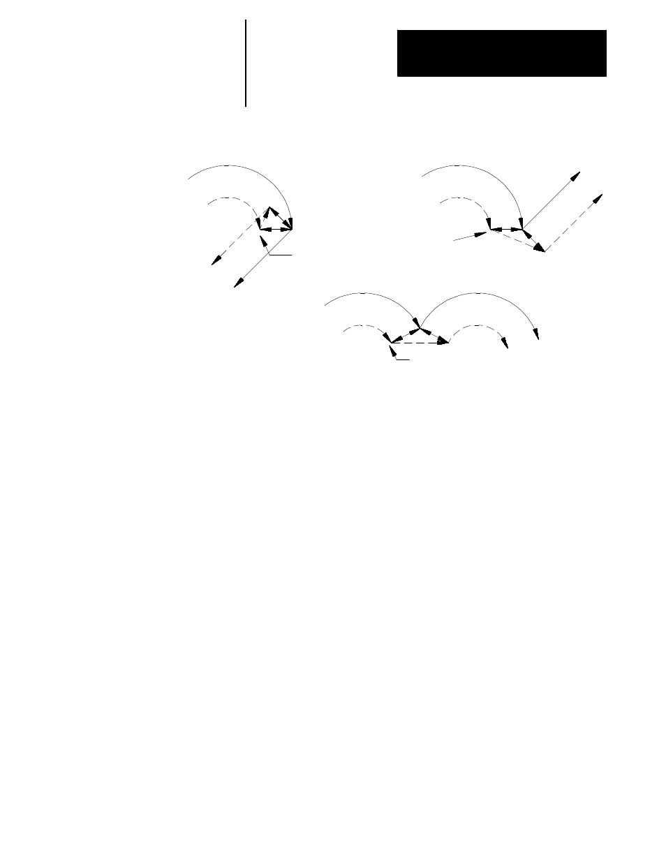
Figure 21.36
Too Many Non-Motion Blocks Following a Circular Move
Too many
non-motion
blocks here
Too many
non-motion
blocks here
Too many non-motion
blocks here
+
+
+
+
r
r
r
r
r
Programmed
path G42
Compensated
path
Programmed
path G42
Compensated
path
Programmed
path G42
Compensated
path
Frequently the control must generate motion blocks to position the cutting
tool in the proper alignment for a following compensated cutting move.
These blocks are generated to make certain that the cutting tool remains at
least one radius of the cutting tool away from the programmed cutting path
at all times.
When the control generates two motion blocks, the length of the first
generated block is checked against a minimum allowable length as
determined in AMP by your system installer. The coordinate values for the
current axes in the compensation plane are compared to the minimum
allowed value. If both are less than the allowed value, then the control
does not executes the first generated block. The path of the second
generated block is then altered to position the cutting tool along a linear
path to the original end-point of the second generated block. See
Figure 21.37 for a pictorial representation.
21.6.3
Corner Movement After
Generated Blocks