Rockwell Automation 8520 9/Series CNC Lathe User Manual
Page 504
Tool Tip Radius Compensation (TTRC)
Function
Chapter 21
21-20
We demonstrate the actual tool paths taken by the cutting tool when using
TTRC type B by pictorial representation. The following subsections
describe the cutter path along with a figure to clarify the description.
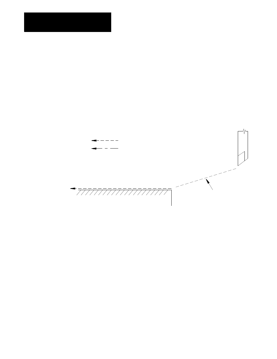
An entry move is defined as the path that the cutting tool takes when the
TTRC function first becomes activated in a program. Figure 21.16 gives
an example of a typical entry move.
Figure 21.16
TTRC Entry Move
Compensation entry move
Workpiece
Programmed tool path
Cutting tool center path
G42 TTRC right
Cutting tool
Important: Any entry move into TTRC must be a linear move. Initial
activation of TTRC by designation of either G41, G42, or T-word in a
circular cutting mode (G02 or G03) is not allowed. The G41 or G42
commands can be designated in a circular block to change TTRC direction,
or a new T-word can be designated to change cutter radius, as long as
TTRC is already active.
The entry move of the cutting tool for type B TTRC can generate extra
motion blocks to attempt to prevent gouging of the part as may sometimes
occur using compensation type A. Type B TTRC keeps the cutting tool at
least one radius away from the start-point of the next block at all times
during an entry move. The final end-point of the entry move is a position
at right angles to and on the left or right side of the next programmed move
in the currently defined plane.
21.4
TTRC Tool Paths (Type B)
21.4.1
TTRC Type B Entry Moves