Rockwell Automation 8520 9/Series CNC Lathe User Manual
Page 577
Compound Turning Routines
Chapter 24
24-13
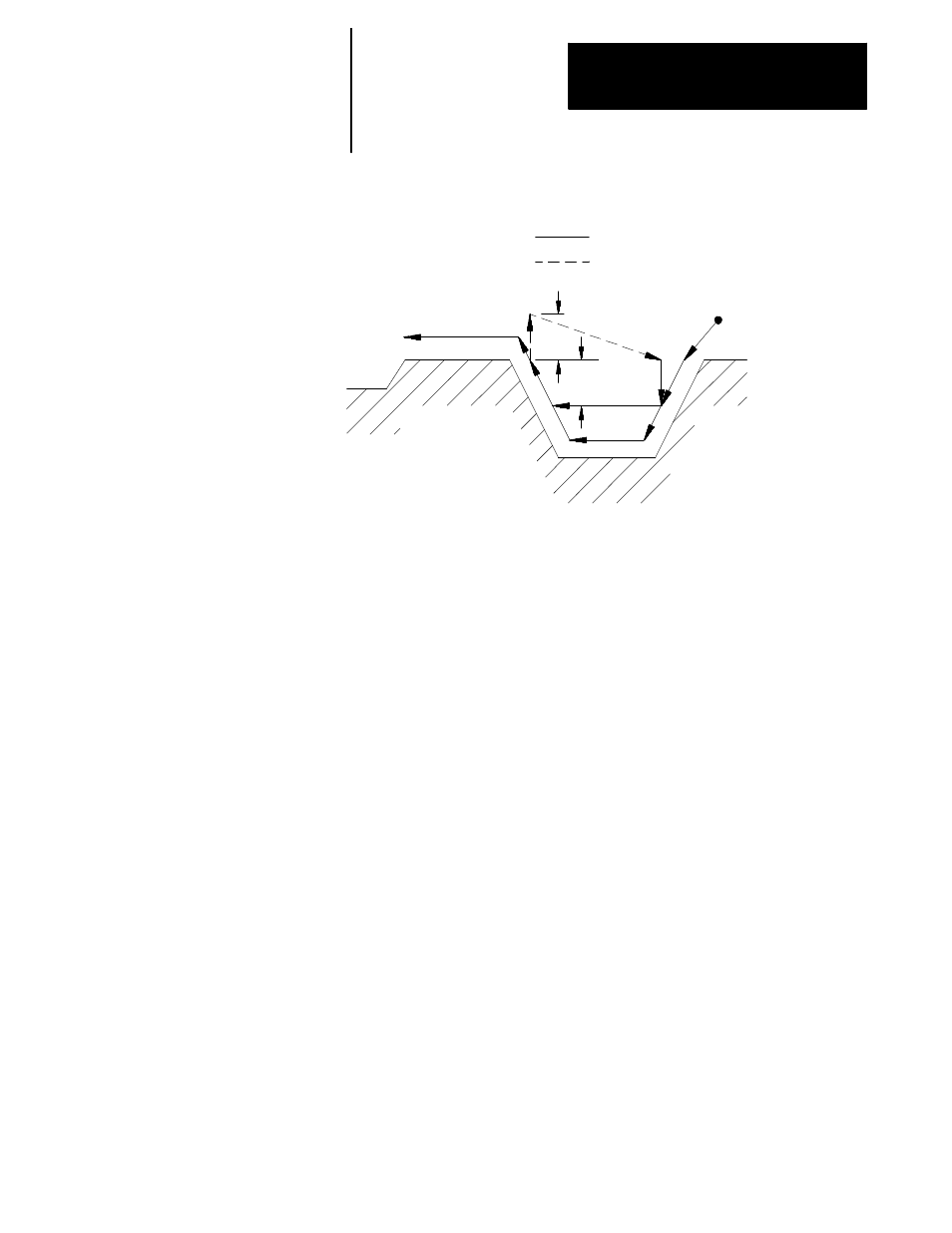
Figure 24.10
Tool Motion in Case 2 G73
Cutting feed
Rapid feed
Start point
1
8
R
D
8
8
8
6
7
4
3
5
2
In Figure 24.10, these tool paths are made:
1.
The tool is moved from the start point to first contour point at
feedrate F. This move must generate motion in both the X and Z
axes.
2.
The control generates a rough cut towards the spindle centerline,
parallel to the workpiece contour, and offset by the finish allowance
amount and the final pass amount (if any). This rough cut continues
until the X axis value has decreased an amount D as programmed in
the G73 block.
3.
A rough cut is made parallel to the Z axis, at a feedrate F, to a point
that intersects with the workpiece contour path minus the finish
allowance and final pass allowance (if any).
4.
A rough cut is made away from the spindle’s centerline, parallel to
the workpiece contour, and offset by the finish allowance amount and
the final pass amount (if any). This rough cut continues, at a feedrate
F, until the X axis value has increased an amount D as programmed
in the G73 block (or until the last contour point is reached).
5.
The tool is retracted from this point, on the X axis only, a distance R
as programmed in the G73 block (or the default distance R set in
AMP) at a feedrate F (see Figure 24.10)
6.
A rapid traverse is made back along the X and Z axes to the Z
coordinate that the last rough cut started from (in step 3) and an X
coordinate that is D distance above the X coordinate of the last
rough cut.