Rockwell Automation 8520 9/Series CNC Lathe User Manual
Page 512
Tool Tip Radius Compensation (TTRC)
Function
Chapter 21
21-28
Figure 21.20 and Figure 21.21 assume that the number of blocks that do
not contain axes motion in the currently selected plane, following G40
before the exit move takes place, do not exceed an amount selected in
AMP by your system installer. If the number of non-motion blocks
following G40 exceeds the limit, the control generates its own exit move.
This may often cause overcutting of the part, since this move is a linear
path directly back to the programmed tool path.
You can modify the path that the tool takes for an exit move by including
an I- and/or K-word in the exit move. Only the I- or K-words that
represent values in the current plane are programmed in the block
containing the exit move. I and K correspond to the X and Z axis
respectively.
The I- and K-words in the exit move block define a vector that the control
uses to redefine the end-point of the previously compensated move.
The vector defined by the I- and/or K-words is along a line drawn from the
end-point of the programmed path through a point programmed with the I-
or K-words. The I- and/or K-words must be in the currently defined plane.
The point defined by I and K is always one incremental distance from the
end-point of the last move measured parallel to the X and Z axis.
A new vector is then defined parallel to the vector defined by the I- and/or
K-word and offset from this vector in the direction and amount of the
currently active offset (G41 or G42). The intersection of this new vector
with the current compensated tool path defines a point which is the new
end-point of the last programmed compensation move.
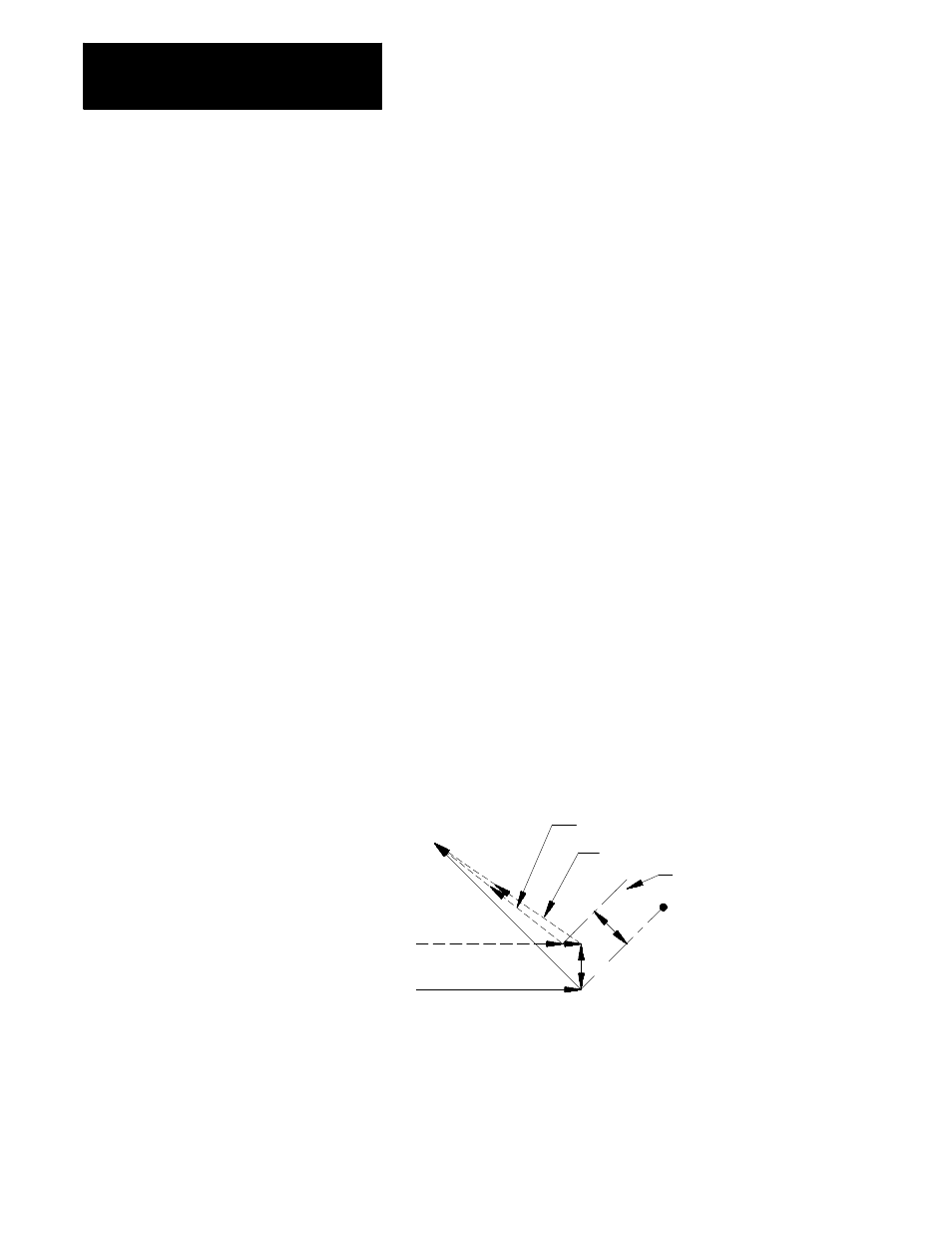
Figure 21.22
Exit Move Defined By An I, K Vector
Compensated path using I, K vector
Compensated path if no I, K in G40 block
Intercept line
I, K
Compensated path
Programmed path
r
r
Figure 21.22 is the exception. The change in length of the compensated
path is more than one radius of the tool. In this case, this offset is limited
to one radius of the tool. The direction of the offset is towards the point of
intersection of the I and/or K vector and the current compensated tool path.