Rockwell Automation 8520 9/Series CNC Lathe User Manual
Page 72
Offset Tables and Setup
Chapter 3
3-4
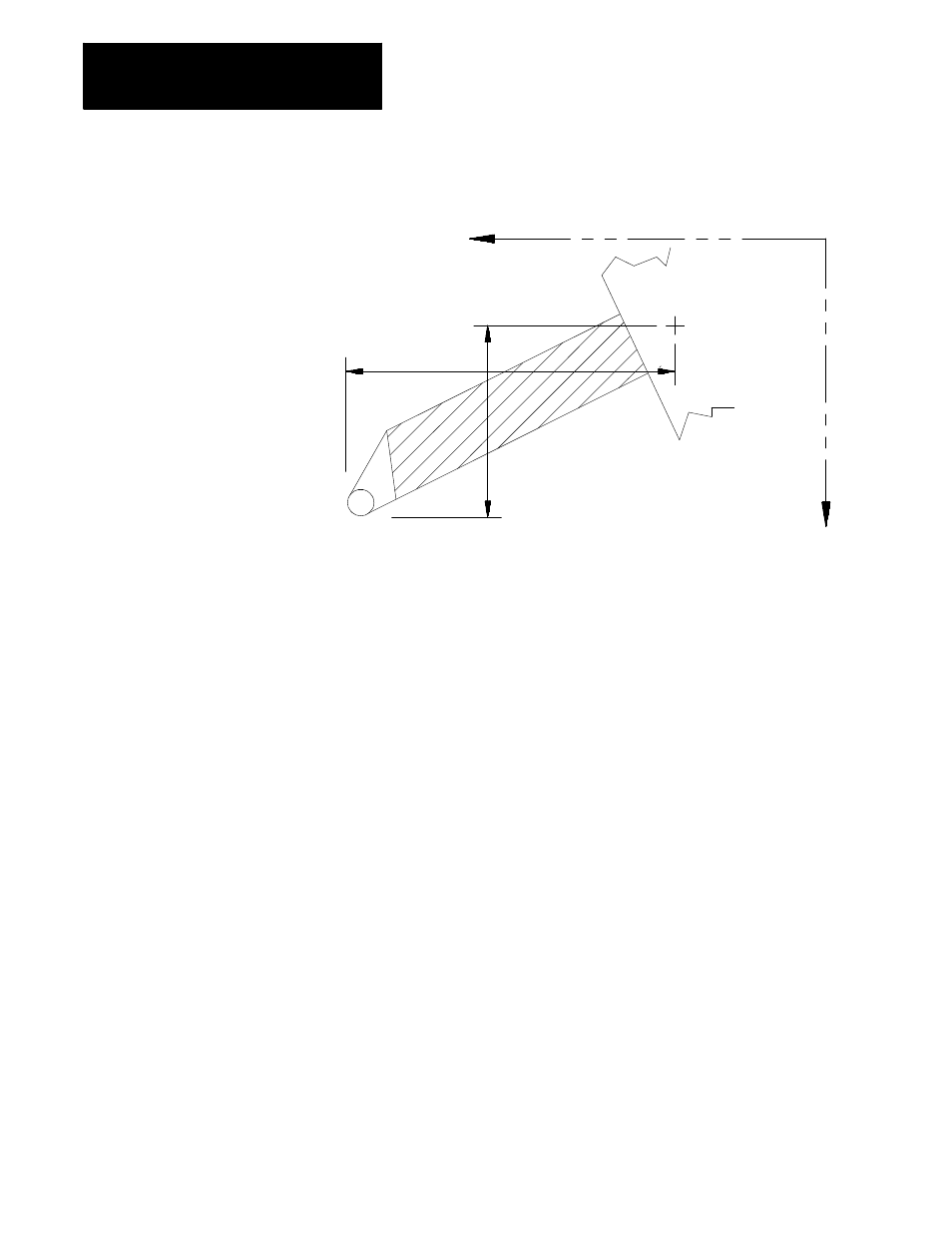
Figure 3.3
Tool Length Offsets
-Z
Z
tool offset
Gauge point
X
tool offset (entered
as a diameter value)
-X
The Z offset table value corresponds to the actual Z distance from the tool
tip to the gauge point. The X offset value is the distance on the axis from
the tool tip to the gauge point. Consequently, when the control activates a
tool offset, the Z axis is displaced per the table value, while the X axis is
displaced half the table value.
Generally machines are configured such that axes move in the negative
direction as they move the tool turret towards the workpiece (this refers to
the main or A turret if a two turret lathe). In that case, if the installed tool
protrudes in the negative direction its offset value is entered as positive.
The tool illustrated in Figure 3.3, for example, extends in both the -X and
-Z directions, so its X and Z offsets would be entered as positive. This
holds true regardless of which turret the tool is on.
Tool Tip Radius - TTR (Tool Geometry Table)
The control can compensate for any cutting error resulting from slight or
even large rounding of the cutting tool tip. To do so, the radius of the
cutting tool tip must be entered as the geometry data for tool tip radius
compensation. For more information, refer to chapter 21.