Rockwell Automation 8520 9/Series CNC Lathe User Manual
Page 70
Offset Tables and Setup
Chapter 3
3-2
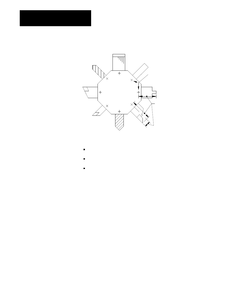
Figure 3.1
Tool Offset
Tool gauge points on turret
from which tool offsets are
usually measured
Tool offset values simplify
programming and allow
processing with different
tools without changing
the part program
You can enter this data into the tool offset tables:
Tool length offset data
{TOOL GEOMET}
and
{TOOL WEAR}
Tool tip radius data
{TOOL GEOMET}
and
{TOOL WEAR}
Tool orientation data
{TOOL GEOMET}
Parameters for the resolution of the offset data are determined by the
system installer in AMP. The range available to the system installer is 0.01
to 0.00001 mm (0.001 to 0.000001 inch) with a maximum number of 8
digits.
Tool Offset Numbers
Use a T-word to call out tool offset numbers in a program. The T-word
specifies a one, two, or three-digit offset number. The control then
accesses the values assigned to that offset number in the table. Offsets are
activated as described in the sections on that specific type of offset.
For more information on calling offset numbers, refer to chapter 20.
Offset number “00” is not valid, but can be used to cancel tool offsets.
Different offset numbers may be called from the tool geometry and tool
wear table using the same T-word (depending on the T-word type selected
in AMP). This means that wear offset data corresponding to offset number
1 may not need to correspond to tool geometry offset number 1, etc.