Rockwell Automation 8520 9/Series CNC Lathe User Manual
Page 18
Manual/MDI Operation Modes
Chapter 1
1-2
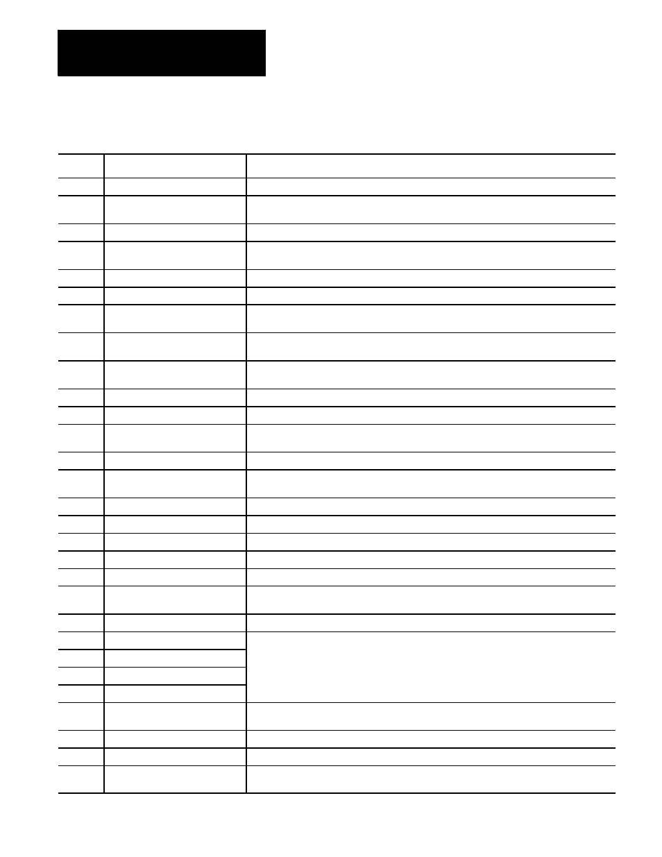
Table 1.A
Manual Organization
Chapter
Title
Summary
1
Manual Overview
Manual overview, intended audience, definition of key terms, how to proceed.
2
Basic Control Operation
A brief description of the control’s basic operation including power up, MTB panel, operator panel,
access control, and E-STOP.
3
Offset Tables and Setup
Basic setup of the offset table, other initial operating parameters.
4
Manual and MDI Operation
How to use the manual operate mode including, homing the machine, jog hand-wheel, jog
continuous, and jog increment. Also covered are the basics for MDI operation.
5
Editing Programs On Line
How to create, edit,and save a part program on line.
6
Editing Part Program Off Line
How to create, edit, and save a part programs from ODS off line.
7
Running a Program
How to select and execute a program automatically. This covers program checking as well as part
production. Also details on special running conditions.
8
Displays/ Graphics
How to access and interpret the different position displays. How to use the Quick Check and Active
Program graphics features.
9
Communications
Communications with peripheral devices. Includes sections on communication port parameters,
inputting and outputting AMP, PAL, Offsets, and programs.
10
Introduction to Programming
Tape format, structure and format of the programming language for the control.
11
Coordinate System Offsets
Machine coordinate system, Preset Work coordinate systems, PAL offsets, and external offsets
12
Overtravels and Programmable
Zones (G22, G23)
Hardware and software overtravels, programmable zone 2 (G22, G23), programmable zone 3
(G22.1, G23.1), and resetting overtravels
13
Coordinate Control
Describes absolute/incremental modes, inch/metric modes, radius/diameter modes, and scaling
14
Axis Motion
G-words define how the tool is positioned to the endpoint of a move. Also sections on automatic
machine home, dwell, mirroring, and axis clamp
15
QuickPath Plus
Describes QuickPath Plus programming
16
Chamfering and Corner Radius
Describes the ,C- and ,R-words programmed for chamfering and corner radius
17
Spindles
Describes spindle speed control, spindle orientation, spindle direction, and Virtual C axis
18
Programming Feedrates
Describes acc/dec, AMP-assigned feedrates, feedrate control, short block acc/dec
19
Dual Axis Operation
Describes parking, homing, programming, offset management for a dual axis
20
Tool Control
Selecting a tool. Activating and deactivating tool length offsets. Also tool control features such as
Random Tool and Tool Life Management.
21
Tool Tip Radius Compensation
Describes the Tool Tip Radius Compensation feature (TTRC) that offsets for different tool diameters.
22
Single--Pass Turning Cycles
Description and use of fixed (canned) cycles for turning operations, and the G--codes and parameters
used to define them.
23
Grooving/Cutoff Cycles
used to define them.
24
Compound Turnign Routines
25
Thread Cutting
26
Drilling Cycles
Description and use of the fixed (canned) cycles for drilling operations and the G--codes and
parameters used to define them.
27
Skip and Gauging Cycles
Describes the 9/Series Probing features. Includes the tool measuring gauge feature.
28
Paramacros
Describes paramacros including calling, arithmetic functions, looping, decision making
29
Program Interrupts
Describes the program interrupt feature. This feature is used to call a subprogram or paramacro
program whenever a signal corresponding to that program is sent to PAL by the operator.