4 smc timings – Rainbow Electronics AT91CAP9S250A User Manual
Page 969
969
6264A–CAP–21-May-07
AT91CAP9S500A/AT91CAP9S250A
47.10.4
SMC Timings
47.10.4.1
Capacitance
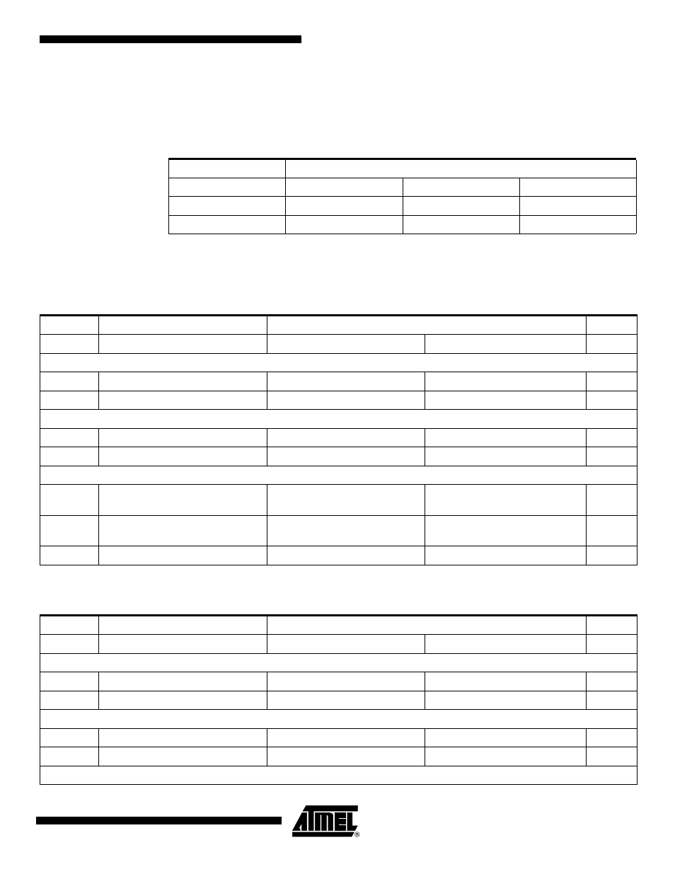
Timings are given assuming a capacitance load on data, control and address pads.
In the following tables, t
CPMCK
is MCK period.
47.10.4.2
Read Timings
Table 47-21. Capacitance Load
Corner
Supply
MAX
STH
MIN
3.3V
50pF
50pF
0 pF
1.8V
30 pF
30 pF
0 pF
Table 47-22. SMC Read Signals - NRD Controlled (READ_MODE= 1)
Symbol
Parameter
Min
Units
VDDIOM supply
1.8V
3.3V
NO HOLD SETTINGS (nrd hold = 0)
SMC
1
Data Setup before NRD High
TBD
TBD
ns
SMC
2
Data Hold after NRD High
TBD
TBD
ns
HOLD SETTINGS (nrd hold
≠
0)
SMC
3
Data Setup before NRD High
TBD
TBD
ns
SMC
4
Data Hold after NRD High
TBD
TBD
ns
HOLD or NO HOLD SETTINGS (nrd hold
≠
0, nrd hold =0)
SMC
5
NBS0/A0, NBS1, NBS2/A1, NBS3,
A2 - A25 Valid before NRD High
(nrd setup + nrd pulse)* t
CPMCK
+
TBD
(nrd setup + nrd pulse)* t
CPMCK
+
TBD
ns
SMC
6
NCS low before NRD High
(nrd setup + nrd pulse - ncs rd
setup) * t
CPMCK
+ TBD
(nrd setup + nrd pulse - ncs rd
setup) * t
CPMCK
+ TBD
ns
SMC
7
NRD Pulse Width
nrd pulse * t
CPMCK
+ TBD
nrd pulse * t
CPMCK
+ TBD
ns
Table 47-23. SMC Read Signals - NCS Controlled (READ_MODE= 0)
Symbol
Parameter
Min
Units
VDDIOM supply
1.8V
3.3V
NO HOLD SETTINGS (ncs rd hold = 0)
SMC
8
Data Setup before NCS High
TBD
TBD
ns
SMC
9
Data Hold after NCS High
TBD
TBD
ns
HOLD SETTINGS (ncs rd hold
≠
0)
SMC
10
Data Setup before NCS High
TBD
TBD
ns
SMC
11
Data Hold after NCS High
TBD
TBD
ns
HOLD or NO HOLD SETTINGS (ncs rd hold
≠
0, ncs rd hold = 0)