Rainbow Electronics AT91CAP9S250A User Manual
Page 441
441
6264A–CAP–21-May-07
AT91CAP9S500A/AT91CAP9S250A
Notes:
1. Reset value of PIO_PSR depends on the product implementation.
2. PIO_ODSR is Read-only or Read/Write depending on PIO_OWSR I/O lines.
3. Reset value of PIO_PDSR depends on the level of the I/O lines. Reading the I/O line levels requires the clock of the PIO
Controller to be enabled, otherwise PIO_PDSR reads the levels present on the I/O line at the time the clock was disabled.
4. PIO_ISR is reset at 0x0. However, the first read of the register may read a different value as input changes may have
occurred.
5. Only this set of registers clears the status by writing 1 in the first register and sets the status by writing 1 in the second
register.
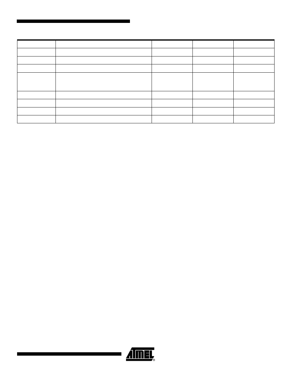
0x0070
Peripheral A Select Register
PIO_ASR
Write-only
–
0x0074
Peripheral B Select Register
PIO_BSR
Write-only
–
0x0078
AB Status Register
PIO_ABSR
Read-only
0x00000000
0x007C
to
0x009C
Reserved
0x00A0
Output Write Enable
PIO_OWER
Write-only
–
0x00A4
Output Write Disable
PIO_OWDR
Write-only
–
0x00A8
Output Write Status Register
PIO_OWSR
Read-only
0x00000000
0x00AC
Reserved
Table 32-2.
Register Mapping (Continued)
Offset
Register
Name
Access
Reset Value