Rainbow Electronics AT91CAP9S250A User Manual
Page 602
602
6264A–CAP–21-May-07
AT91CAP9S500A/AT91CAP9S250A
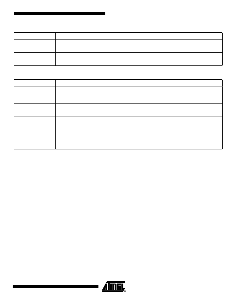
• CKG: Transmit Clock Gating Selection
• START: Transmit Start Selection
• STTDLY: Transmit Start Delay
If STTDLY is not 0, a delay of STTDLY clock cycles is inserted between the start event and the actual start of transmission
of data. When the Transmitter is programmed to start synchronously with the Receiver, the delay is also applied.
Note: STTDLY must be set carefully. If STTDLY is too short in respect to TAG (Transmit Sync Data) emission, data is emit-
ted instead of the end of TAG.
• PERIOD: Transmit Period Divider Selection
This field selects the divider to apply to the selected Transmit Clock to generate a new Frame Sync Signal. If 0, no period
signal is generated. If not 0, a period signal is generated at each 2 x (PERIOD+1) Transmit Clock.
CKG
Transmit Clock Gating
0x0
None, continuous clock
0x1
Transmit Clock enabled only if TF Low
0x2
Transmit Clock enabled only if TF High
0x3
Reserved
START
Transmit Start
0x0
Continuous, as soon as a word is written in the SSC_THR Register (if Transmit is enabled), and
immediately after the end of transfer of the previous data.
0x1
Receive start
0x2
Detection of a low level on TF signal
0x3
Detection of a high level on TF signal
0x4
Detection of a falling edge on TF signal
0x5
Detection of a rising edge on TF signal
0x6
Detection of any level change on TF signal
0x7
Detection of any edge on TF signal
0x8 - 0xF
Reserved