Rainbow Electronics AT91CAP9S250A User Manual
Page 625
625
6264A–CAP–21-May-07
AT91CAP9S500A/AT91CAP9S250A
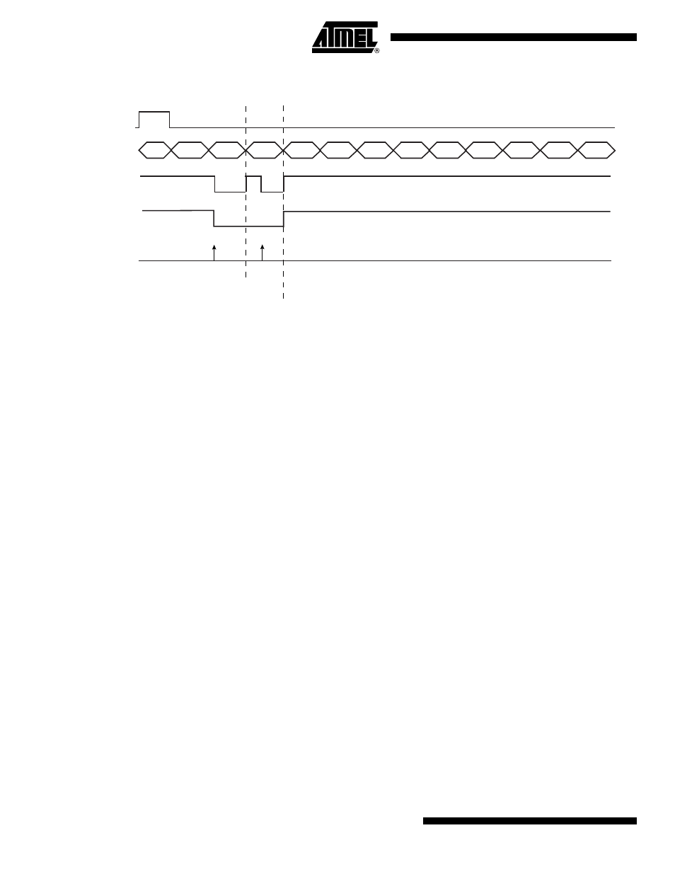
Figure 37-5. Audio Transfer (PCM L Front, PCM R Front) on Channel x
The TXEMPTY flag in the AC’97 Controller Channel x Status Register (AC97C_CxSR) is set
when all requested transmissions for a channel have been shifted on the AC-link. The applica-
tion can either poll TXEMPTY flag in AC97C_CxSR or wait for an interrupt notice associated
with the same flag.
In most cases, the AC’97 Controller is embedded in chips that target audio player devices. In
such cases, the AC‘97 Controller is exposed to heavy audio transfers. Using the polling tech-
nique increases processor overhead and may fail to keep the required pace under an
operating system. In order to avoid these polling drawbacks, the application can perform audio
streams by using PDC connected to channel A, which reduces processor overhead and
increases performance especially under an operating system.
The PDC transmit counter values must be equal to the number of PCM samples to be trans-
mitted, each sample goes in one slot.
37.6.2.3
AC‘97 Output Frame
The AC’97 Controller outputs a thirteen-slot frame on the AC-Link. The first slot (tag slot or slot
0) flags the validity of the entire frame and the validity of each slot; whether a slot carries valid
data or not. Slots 1 and 2 are used if the application performs control and status monitoring
actions on AC97 Codec control/status registers. Slots [3:12] are used according to the content
of the AC’97 Controller Output Channel Assignment Register (AC97C_OCA). If the application
performs many transmit requests on a channel, some of the slots associated to this channel or
all of them will carry valid data.
37.6.2.4
Receive Operation
The AC’97 Controller can also receive data from AC‘97 Codec. Data is received in the chan-
nel’s shift register and then transferred to the AC’97 Controller Channel x Read Holding
Register. To read the newly received data, the application must perform the following steps:
• Poll RXRDY flag in AC’97 Controller Channel x Status Register (AC97C_CxSR). x being
one of the 3 channels.
• Read data from AC’97 Controller Channel x Read Holding Register.
Slot #
AC97FS
TAG
CMD
ADDR
CMD
DATA
0
AC97TX
(Controller Output)
PCM
L Front
PCM
R Front
LINE 1
DAC
PCM
Center
PCM
L SURR
PCM
R SURR
PCM
LFE
LINE 2
DAC
HSET
DAC
IO
CTRL
1
2
3
4
5
6
7
8
9
10
11
12
TXRDYCx
(AC97C_SR)
Write access to
AC97C_THRx
PCM L Front
transfered to the shift register
PCM R Front
transfered to the shift register
TXEMPTY
(AC97C_SR)