6 rs485 mode – Rainbow Electronics AT91CAP9S250A User Manual
Page 556
556
6264A–CAP–21-May-07
AT91CAP9S500A/AT91CAP9S250A
35.6.6
RS485 Mode
The USART features the RS485 mode to enable line driver control. While operating in RS485
mode, the USART behaves as though in asynchronous or synchronous mode and configuration
of all the parameters is possible. The difference is that the RTS pin is driven high when the
transmitter is operating. The behavior of the RTS pin is controlled by the TXEMPTY bit. A typical
connection of the USART to a RS485 bus is shown in
.
Figure 35-36. Typical Connection to a RS485 Bus
The USART is set in RS485 mode by programming the USART_MODE field in the Mode Regis-
ter (US_MR) to the value 0x1.
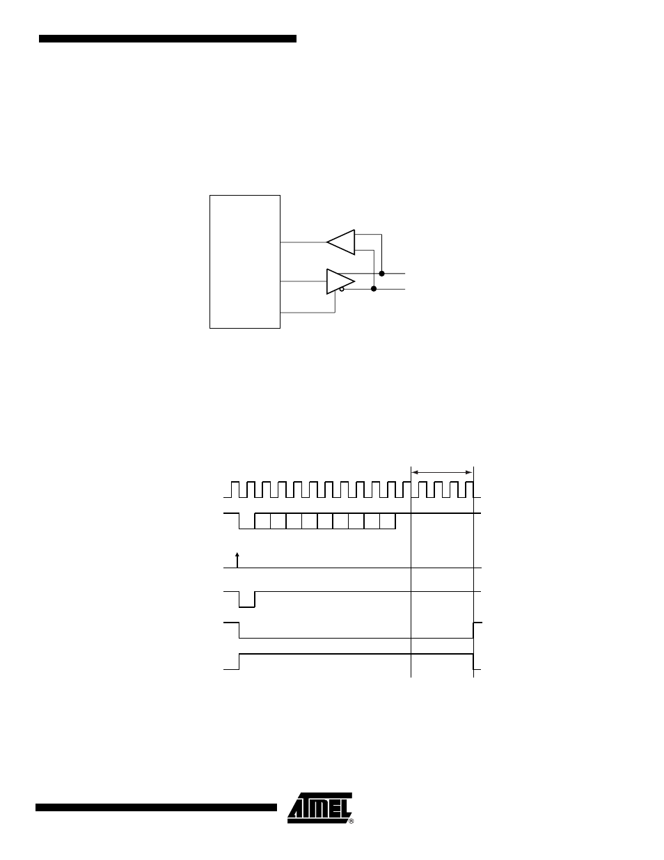
The RTS pin is at a level inverse to the TXEMPTY bit. Significantly, the RTS pin remains high
when a timeguard is programmed so that the line can remain driven after the last character com-
pletion.
gives an example of the RTS waveform during a character transmission
when the timeguard is enabled.
Figure 35-37. Example of RTS Drive with Timeguard
USART
RTS
TXD
RXD
Differential
Bus
D0
D1
D2
D3
D4
D5
D6
D7
TXD
Start
Bit
Parity
Bit
Stop
Bit
Baud Rate
Clock
TG = 4
Write
US_THR
TXRDY
TXEMPTY
RTS