Table 23-7, Width – Rainbow Electronics AT91CAP9S250A User Manual
Page 231
231
6264A–CAP–21-May-07
AT91CAP9S500A/AT91CAP9S250A
Note:
1. SDR-SDRAM devices with eight columns in 16-bit mode are not supported.
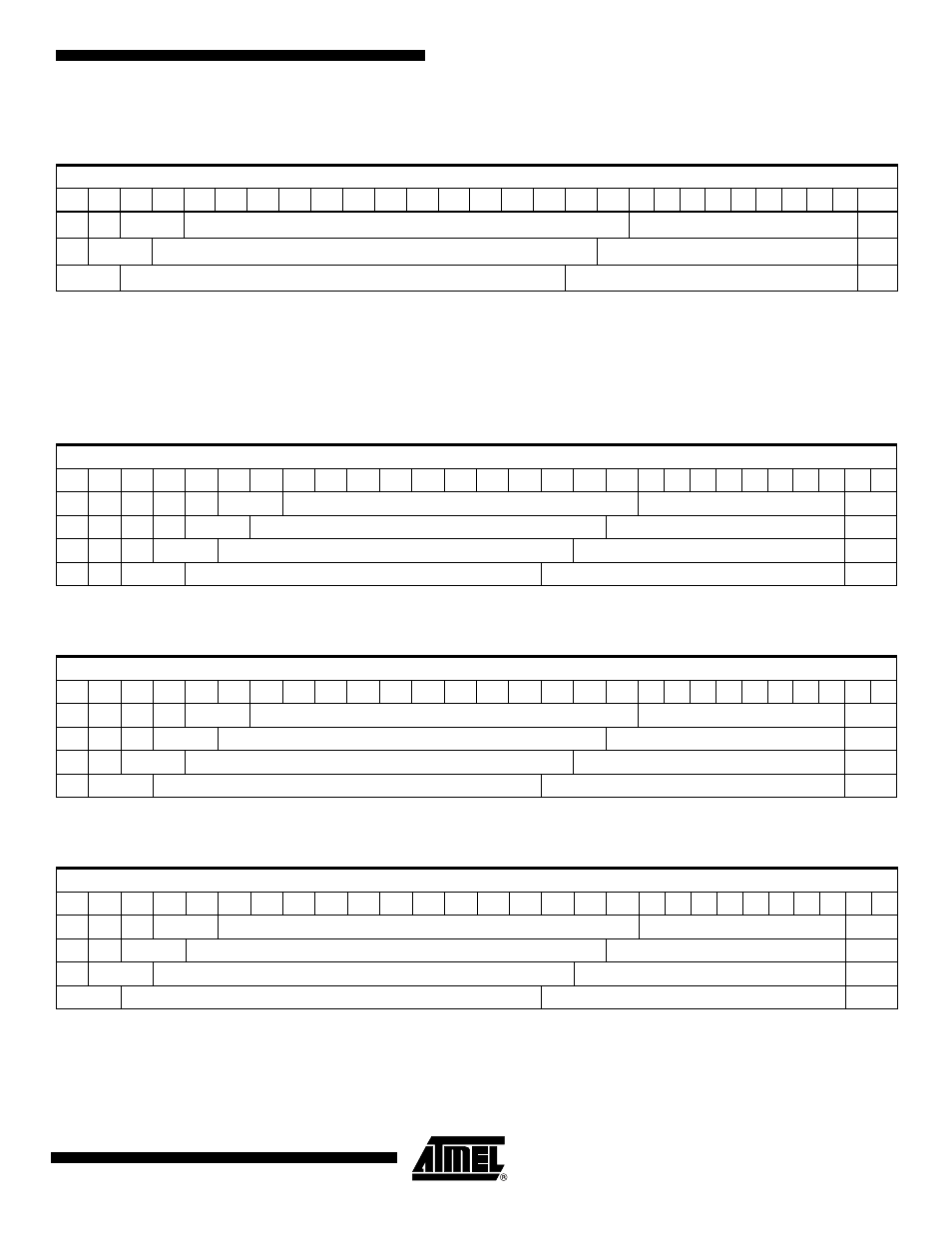
23.5.2
SDR-SDRAM Address Mapping for 32-bit Memory Data Bus Width
Notes:
1. M[1:0] is the byte address inside a 32-bit word.
2. Bk[1] = BA1, Bk[0] = BA0
Table 23-4.
Linear Mapping for SDRAM Configuration: 16K Rows, 512/1024/2048 Columns
CPU Address Line
27
26
25
24
23
22
21
20
19
18
17
16
15
14
13
12
11
10
9
8
7
6
5
4
3
2
1
0
Bk[1:0]
Row[13:0]
Column[8:0]
M0
Bk[1:0]
Row[13:0]
Column[9:0]
M0
Bk[1:0]
Row[13:0]
Column[10:0]
M0
Table 23-5.
SDR-SDRAM Configuration Mapping: 2K Rows, 256/512/1024/2048 Columns
CPU Address Line
27
26
25
24
23
22
21
20
19
18
17
16
15
14
13
12
11
10
9
8
7
6
5
4
3
2
1
0
Bk[1:0]
Row[10:0]
Column[7:0]
M[1:0]
Bk[1:0]
Row[10:0]
Column[8:0]
M[1:0]
Bk[1:0]
Row[10:0]
Column[9:0]
M[1:0]
Bk[1:0]
Row[10:0]
Column[10:0]
M[1:0]
Table 23-6.
SDR-SDRAM Configuration Mapping: 4K Rows, 256/512/1024/2048 Columns
CPU Address Line
27
26
25
24
23
22
21
20
19
18
17
16
15
14
13
12
11
10
9
8
7
6
5
4
3
2
1
0
Bk[1:0]
Row[11:0]
Column[7:0]
M[1:0]
Bk[1:0]
Row[11:0]
Column[8:0]
M[1:0]
Bk[1:0]
Row[11:0]
Column[9:0]
M[1:0]
Bk[1:0]
Row[11:0]
Column[10:0]
M[1:0]
Table 23-7.
SDR-SDRAM Configuration Mapping: 8K Rows, 256/512/1024/2048 Columns
CPU Address Line
27
26
25
24
23
22
21
20
19
18
17
16
15
14
13
12
11
10
9
8
7
6
5
4
3
2
1
0
Bk[1:0]
Row[12:0]
Column[7:0]
M[1:0]
Bk[1:0]
Row[12:0]
Column[8:0]
M[1:0]
Bk[1:0]
Row[12:0]
Column[9:0]
M[1:0]
Bk[1:0]
Row[12:0]
Column[10:0]
M[1:0]