7 hardware and software constraints – Rainbow Electronics AT91CAP9S250A User Manual
Page 82
82
6264A–CAP–21-May-07
AT91CAP9S500A/AT91CAP9S250A
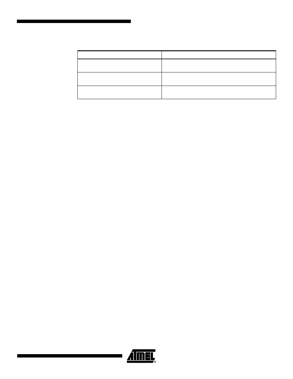
The device also handles some class requests defined in the CDC class.
Unhandled requests are STALLed.
14.6.3.2
Communication Endpoints
There are two communication endpoints and endpoint 0 is used for the enumeration process.
Endpoint 1 is a 64-byte Bulk OUT endpoint and endpoint 2 is a 64-byte Bulk IN endpoint.
SAM-BA Boot commands are sent by the host through the endpoint 1. If required, the mes-
sage is split by the host into several data payloads by the host driver.
If the command requires a response, the host can send IN transactions to pick up the
response.
14.7
Hardware and Software Constraints
• The DataFlash and NANDFlash downloaded code size must be inferior to 28 Kbytes.
• The code is always downloaded from the device address 0x0000_0000 to the address
0x0000_0000 of the internal SRAM (after remap).
• The downloaded code must be position-independent or linked at address 0x0000_0000.
• The DataFlash must be connected to NPCS0 of the SPI.
The SPI and NANDFlash drivers use several PIOs in alternate functions to communicate with
devices. Care must be taken when these PIOs are used by the application. The devices con-
nected could be unintentionally driven at boot time, and electrical conflicts between SPI output
pins and the connected devices may appear.
To assure correct functionality, it is recommended to plug in critical devices to other pins.
contains a list of pins that are driven during the boot program execution. These
pins are driven during the boot sequence for a period of less than 1 second if no correct boot
program is found.
For the DataFlash driven by the SPCK signal at 8 MHz, the time to download 28 Kbytes is
reduced to 200 ms.
Table 14-6.
Handled Class Requests
Request
Definition
SET_LINE_CODING
Configures DTE rate, stop bits, parity and number of
character bits.
GET_LINE_CODING
Requests current DTE rate, stop bits, parity and number
of character bits.
SET_CONTROL_LINE_STATE
RS-232 signal used to tell the DCE device the DTE
device is now present.