4 pmc peripheral clock enable register, 5 pmc peripheral clock disable register – Rainbow Electronics AT91CAP9S250A User Manual
Page 369
369
6264A–CAP–21-May-07
AT91CAP9S500A/AT91CAP9S250A
29.9.4
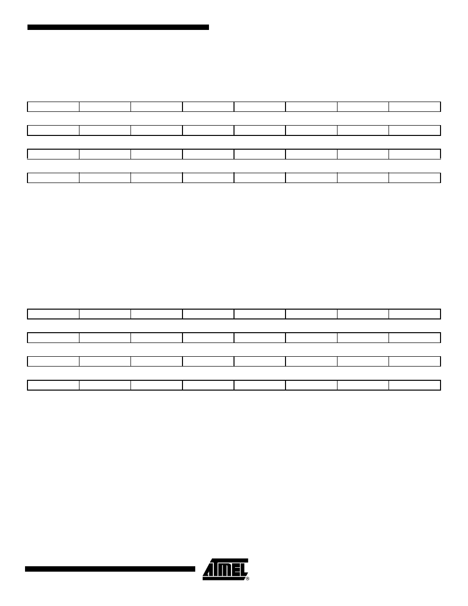
PMC Peripheral Clock Enable Register
Register Name:
PMC_PCER
Access Type:
Write-only
• PIDx: Peripheral Clock x Enable
0 = No effect.
1 = Enables the corresponding peripheral clock.
Note:
PID2 to PID31 refer to identifiers as defined in the section “Peripheral Identifiers” in the product datasheet.
Note:
Programming the control bits of the Peripheral ID that are not implemented has no effect on the behavior of the PMC.
29.9.5
PMC Peripheral Clock Disable Register
Register Name:
PMC_PCDR
Access Type:
Write-only
• PIDx: Peripheral Clock x Disable
0 = No effect.
1 = Disables the corresponding peripheral clock.
Note:
PID2 to PID31 refer to identifiers as defined in the section “Peripheral Identifiers” in the product datasheet.
31
30
29
28
27
26
25
24
PID31
PID30
PID29
PID28
PID27
PID26
PID25
PID24
23
22
21
20
19
18
17
16
PID23
PID22
PID21
PID20
PID19
PID18
PID17
PID16
15
14
13
12
11
10
9
8
PID15
PID14
PID13
PID12
PID11
PID10
PID9
PID8
7
6
5
4
3
2
1
0
PID7
PID6
PID5
PID4
PID3
PID2
-
-
31
30
29
28
27
26
25
24
PID31
PID30
PID29
PID28
PID27
PID26
PID25
PID24
23
22
21
20
19
18
17
16
PID23
PID22
PID21
PID20
PID19
PID18
PID17
PID16
15
14
13
12
11
10
9
8
PID15
PID14
PID13
PID12
PID11
PID10
PID9
PID8
7
6
5
4
3
2
1
0
PID7
PID6
PID5
PID4
PID3
PID2
-
-