Rainbow Electronics AT91CAP9S250A User Manual
Page 587
587
6264A–CAP–21-May-07
AT91CAP9S500A/AT91CAP9S250A
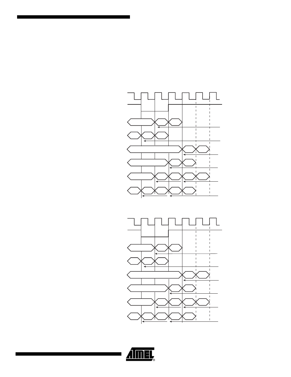
A start can be programmed in the same manner on either side of the Transmit/Receive Clock
Register (RCMR/TCMR). Thus, the start could be on TF (Transmit) or RF (Receive).
Moreover, the Receiver can start when data is detected in the bit stream with the Compare
Functions.
Detection on TF/RF input/output is done by the field FSOS of the Transmit/Receive Frame Mode
Register (TFMR/RFMR).
Figure 36-10. Transmit Start Mode
Figure 36-11. Receive Pulse/Edge Start Modes
X
TK
TF
(Input)
TD
(Output)
TD
(Output)
TD
(Output)
TD
(Output)
TD
(Output)
TD
(Output)
X
BO
B1
X
BO
B1
BO
B1
BO
B1
BO
B1
BO
B1
BO
B1
B1
BO
X
X
X
STTDLY
STTDLY
STTDLY
STTDLY
STTDLY
STTDLY
Start = Falling Edge on TF
Start = Rising Edge on TF
Start = Low Level on TF
Start = High Level on TF
Start = Any Edge on TF
Start = Level Change on TF
X
RK
RF
(Input)
RD
(Input)
RD
(Input)
RD
(Input)
RD
(Input)
RD
(Input)
RD
(Input)
X
BO
B1
X
BO
B1
BO
B1
BO
B1
BO
B1
BO
B1
BO
B1
B1
BO
X
X
X
STTDLY
STTDLY
STTDLY
STTDLY
STTDLY
STTDLY
Start = Falling Edge on RF
Start = Rising Edge on RF
Start = Low Level on RF
Start = High Level on RF
Start = Any Edge on RF
Start = Level Change on RF