5 ssc transmit clock mode register – Rainbow Electronics AT91CAP9S250A User Manual
Page 601
601
6264A–CAP–21-May-07
AT91CAP9S500A/AT91CAP9S250A
36.8.5
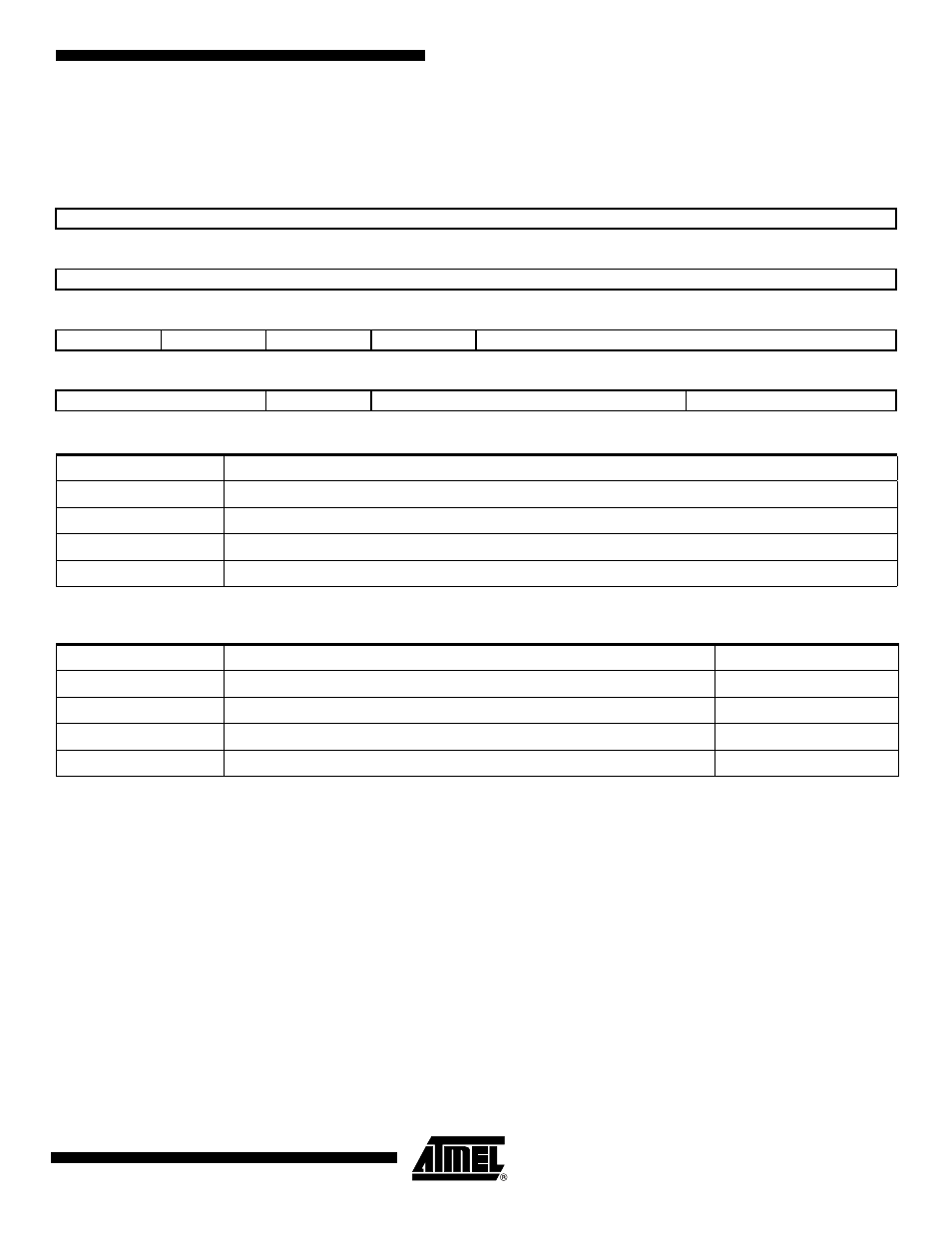
SSC Transmit Clock Mode Register
Name:
SSC_TCMR
Access Type:
Read/Write
• CKS: Transmit Clock Selection
• CKO: Transmit Clock Output Mode Selection
• CKI: Transmit Clock Inversion
0: The data outputs (Data and Frame Sync signals) are shifted out on Transmit Clock falling edge. The Frame sync signal
input is sampled on Transmit clock rising edge.
1: The data outputs (Data and Frame Sync signals) are shifted out on Transmit Clock rising edge. The Frame sync signal
input is sampled on Transmit clock falling edge.
CKI affects only the Transmit Clock and not the output clock signal.
31
30
29
28
27
26
25
24
PERIOD
23
22
21
20
19
18
17
16
STTDLY
15
14
13
12
11
10
9
8
–
–
–
–
START
7
6
5
4
3
2
1
0
CKG
CKI
CKO
CKS
CKS
Selected Transmit Clock
0x0
Divided Clock
0x1
RK Clock signal
0x2
TK Pin
0x3
Reserved
CKO
Transmit Clock Output Mode
TK pin
0x0
None
Input-only
0x1
Continuous Transmit Clock
Output
0x2
Transmit Clock only during data transfers
Output
0x3-0x7
Reserved