3 dataflash boot sequence – Rainbow Electronics AT91CAP9S250A User Manual
Page 77
77
6264A–CAP–21-May-07
AT91CAP9S500A/AT91CAP9S250A
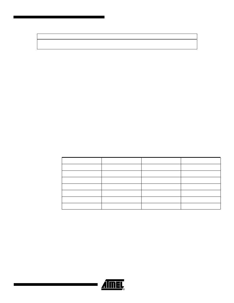
Figure 14-5. Structure of the ARM Vector 6
14.4.2.1
Example
An example of valid vectors follows:
00
ea000006
B
0x20
04
eafffffe
B
0x04
08
ea00002f
B
_main
0c
eafffffe
B
0x0c
10
eafffffe
B
0x10
14
00001234
B
0x14
<- Code size = 4660 bytes
18
eafffffe
B
0x18
The size of the image to load into SRAM is contained in the location of the sixth ARM vector.
Thus the user must replace this vector by the correct vector for his application.
14.4.3
DataFlash Boot Sequence
The DataFlash Boot program performs device initialization followed by the download
procedure.
The DataFlash Boot program supports all Atmel DataFlash devices.
summarizes
the parameters to include in the ARM vector 6 for all devices.
The DataFlash has a Status Register that determines all the parameters required to access
the device. The DataFlash Boot is configured to be compatible with the future design of the
DataFlash.
31
0
Size of the code to download in bytes
Table 14-2.
DataFlash Device
Device
Density
Page Size (bytes)
Number of Pages
AT45DB011B
1 Mbit
264
512
AT45DB021B
2 Mbits
264
1024
AT45DB041B
4 Mbits
264
2048
AT45DB081B
8 Mbits
264
4096
AT45DB161B
16 Mbits
528
4096
AT45DB321B
32 Mbits
528
8192
AT45DB642
64 Mbits
1056
8192