3 device initialization – Rainbow Electronics AT91CAP9S250A User Manual
Page 75
75
6264A–CAP–21-May-07
AT91CAP9S500A/AT91CAP9S250A
14.3
Device Initialization
Initialization follows the steps described below:
1.
Stack setup for ARM supervisor mode
2.
Main Oscillator Frequency Detection
3.
C variable initialization
4.
PLL setup: PLLB is initialized to generate a 48 MHz clock necessary to use the USB
Device. A register located in the Power Management Controller (PMC) determines
the frequency of the main oscillator and thus the correct factor for the PLLB.
defines the crystals supported by the Boot Program.
5.
Initialization of the DBGU serial port (115200 bauds, 8, N, 1)
6.
Enable the user reset
7.
Jump to DataFlash Boot sequence through NPCS0. If DataFlash Boot succeeds, per-
form a remap and jump to 0x0.
8.
Jump to NANDFlash Boot sequence. If NANDFlash Boot succeeds, perform a remap
and jump to 0x0.
9.
Activation of the Instruction Cache
10. Jump to SAM-BA Boot sequence
11. Disable the Watchdog
12. Initialization of the USB Device Port
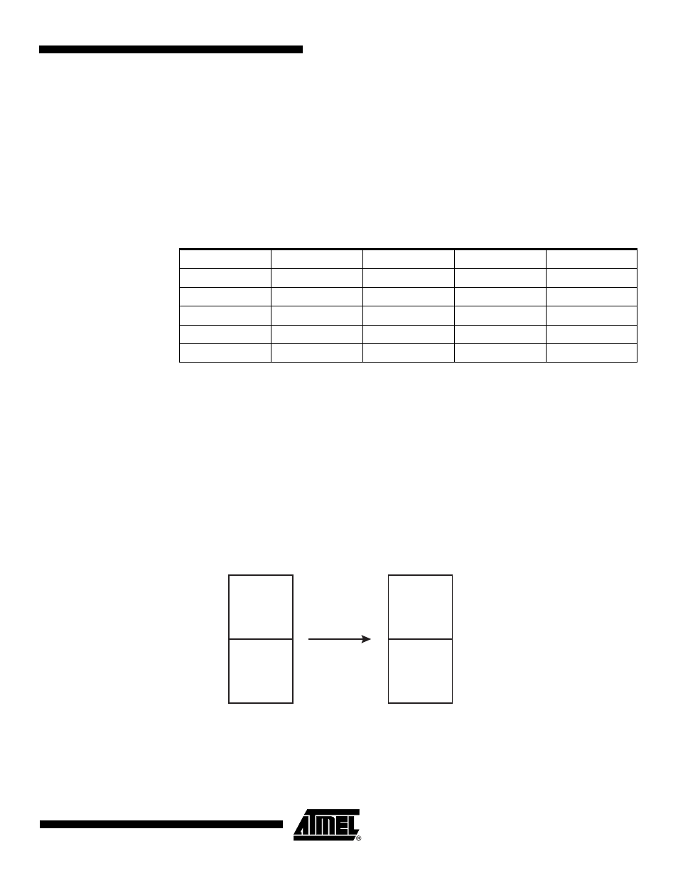
Figure 14-2. Remap Action after Download Completion
Table 14-1.
Crystals Supported by Software Auto-Detection (MHz)
3.0
3.2768
3.6864
3.84
4.0
4.433619
4.608
4.9152
5.0
5.24288
6.0
6.144
6.4
6.5536
7.159090
7.3728
7.864320
8.0
9.8304
10.0
11.05920
12.0
12.288
13.56
14.31818
14.7456
16.0
17.734470
18.432
20.0
REMAP
Internal
ROM
Internal
SRAM
Internal
SRAM
Internal
ROM
0x0010_0000
0x0000_0000
0x0040_0000
0x0000_0000