Rainbow Electronics AT91CAP9S250A User Manual
Page 259
259
6264A–CAP–21-May-07
AT91CAP9S500A/AT91CAP9S250A
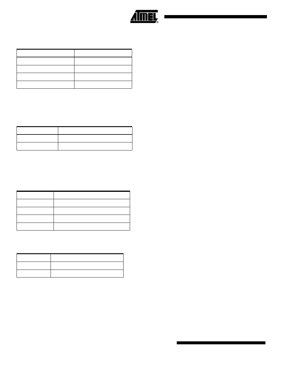
This field manages the row boundaries. Some Cellular Ram providers do not provide the number of words in row in their
devices, in this case the reset value is used.
• ADDRDATA_MUX
Reset Value is 0.
This field is used to multiplex the address and data bus. This feature is reserved for Cellular Ram version 2.0. In the case
of Cellular Ram version 1.0, 1.5 the value is 0.
• DS: Drive Strength
Reset Value is 0.
This field is used to select the driver strength of Cellular Ram output.
The table below gives an example and can change with the Cellular Ram provider.
• VAR_FIX_LAT: Variable Latency or Fixed Latency
The Reset Value is 0, variable latency.
This feature is reserved for Cellular Ram version 1.5/2.0. In the case of Cellular Ram version 1.0 the value is 0.
In the variable latency mode, the latency programmed in the bus configuration register is not guaranteed, it is maintained
only if there is no refresh collision. The wait signal must be monitored.
In the fixed latency mode, the first data outputs conform to the fixed timing, including refresh collision. The wait signal can
be unmonitored. This mode is of benefit for applications with low clock frequency.
Boundary Word
Number of Words in Row
00
64
01
128
10
256
11
512
ADDRDTAT_MUX
0
address data bus not multiplexed
1
address data bus multiplexed
DS
Drive Strength
00
full
01
1/2
10
1/4
11
reserved
VAR_FIX_LAT
0
variable latency
1
fixed latency