11 external wait, 1 restriction, Figure 22-25 – Rainbow Electronics AT91CAP9S250A User Manual
Page 193: Illustrate
193
6264A–CAP–21-May-07
AT91CAP9S500A/AT91CAP9S250A
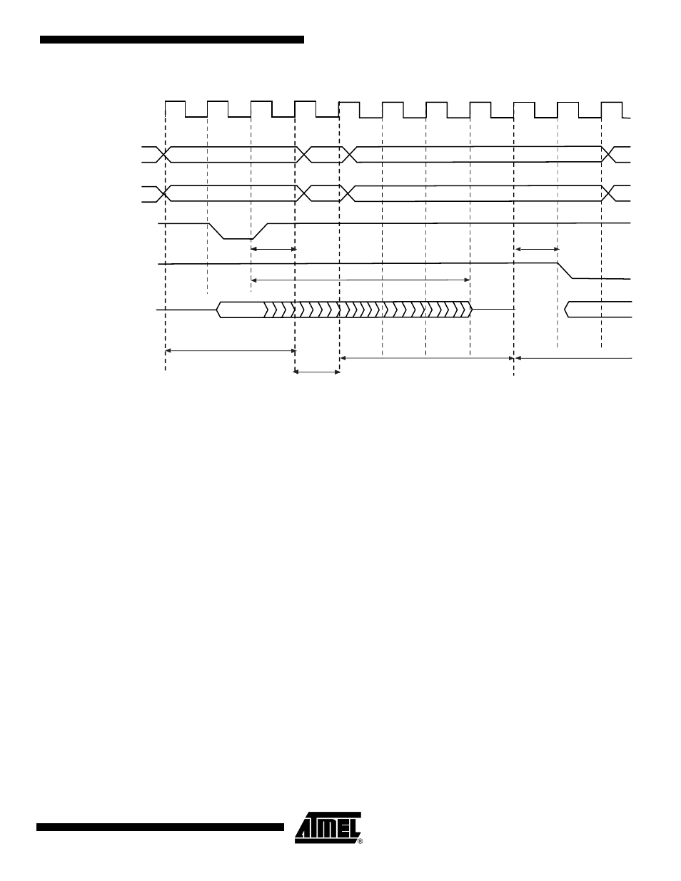
Figure 22-25. TDF Mode = 0: TDF wait states between read and write accesses on the same chip select
22.11 External Wait
Any access can be extended by an external device using the NWAIT input signal of the SMC.
The EXNW_MODE field of the SMC_MODE register on the corresponding chip select must be
set to either to “10” (frozen mode) or “11” (ready mode). When the EXNW_MODE is set to “00”
(disabled), the NWAIT signal is simply ignored on the corresponding chip select. The NWAIT
signal delays the read or write operation in regards to the read or write controlling signal,
depending on the read and write modes of the corresponding chip select.
22.11.1
Restriction
When one of the EXNW_MODE is enabled, it is mandatory to program at least one hold
cycle for the read/write controlling signal. For that reason, the NWAIT signal cannot be
used in Page Mode (
“Asynchronous Page Mode” on page 202
), or in Slow Clock Mode
(
The NWAIT signal is assumed to be a response of the external device to the read/write request
of the SMC. Then NWAIT is examined by the SMC only in the pulse state of the read or write
controlling signal. The assertion of the NWAIT signal outside the expected period has no impact
on SMC behavior.
TDF_CYCLES = 5
TDF_CYCLES = 5
TDF_MODE = 0
(optimization disabled)
A
[25:2]
read1 cycle
Read to Write
Wait State
MCK
read1 controlling signal
(NRD)
write2 controlling signal
(NWE)
D[31:0]
read1 hold = 1
write2 cycle
write2 setup = 1
4 TDF WAIT STATES
NBS0, NBS1,
NBS2, NBS3,
A0, A1