5 endpoint configuration – Rainbow Electronics AT91CAP9S250A User Manual
Page 851
851
6264A–CAP–21-May-07
AT91CAP9S500A/AT91CAP9S250A
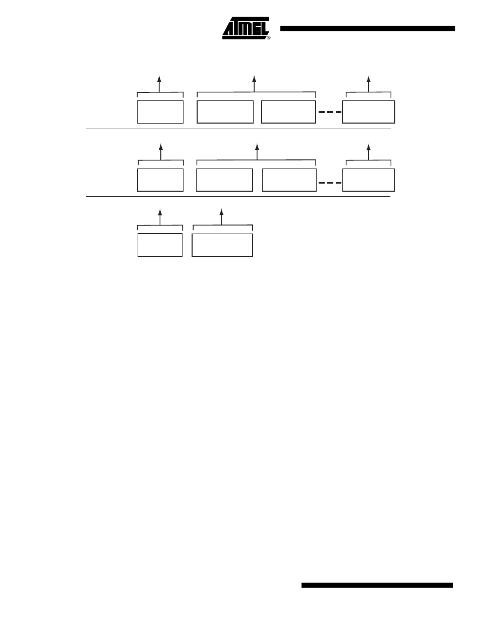
Figure 44-3. Control Read and Write Sequences
A status IN or OUT transaction is identical to a data IN or OUT transaction.
44.4.5
Endpoint Configuration
The endpoint 0 is always a control endpoint, it must be programmed and active in order to be
enabled when the End Of Reset interrupt occurs.
To configure the endpoints:
• Fill the configuration register (UDPHS_EPTCFG) with the endpoint size, direction (IN or
OUT), type (CTRL, Bulk, IT, ISO) and the number of banks.
• Fill the number of transactions (NB_TRANS) for isochronous endpoints.
Note: For control endpoints the direction has no effect.
• Verify that the EPT_MAPD flag is set. This flag is set if the endpoint size and the number of
banks are correct compared to the FIFO maximum capacity and the maximum number of
allowed banks.
• Configure control flags of the endpoint and enable it in UDPHS_EPTCTLENBx according to
“UDPHS Endpoint Control Register” on page 893
Control endpoints can generate interrupts and use only 1 bank.
All endpoints (except endpoint 0) can be configured either as Bulk, Interrupt or Isochronous. See
Table 44-1. UDPHS Endpoint Description
.
The maximum packet size they can accept corresponds to the maximum endpoint size.
Note: The endpoint size of 1024 is reserved for isochronous endpoints.
The size of the DPRAM is 4
KB. The DPR is shared by all active endpoints. The memory size
required by the active endpoints must not exceed the size of the DPRAM.
SIZE_DPRAM = SIZE _EPT0
Control Write
Setup TX
Data OUT TX
Data OUT TX
Data Stage
Control Read
Setup Stage
Setup Stage
Setup TX
Setup TX
No Data
Control
Data IN TX
Data IN TX
Status Stage
Status Stage
Status IN TX
Status OUT TX
Status IN TX
Data Stage
Setup Stage
Status Stage