3 variable sample rate – Rainbow Electronics AT91CAP9S250A User Manual
Page 628
628
6264A–CAP–21-May-07
AT91CAP9S500A/AT91CAP9S250A
Data emitted on related slot: data[19:0] = {0x000, Byte1[1:0], Byte0[7:0]}.
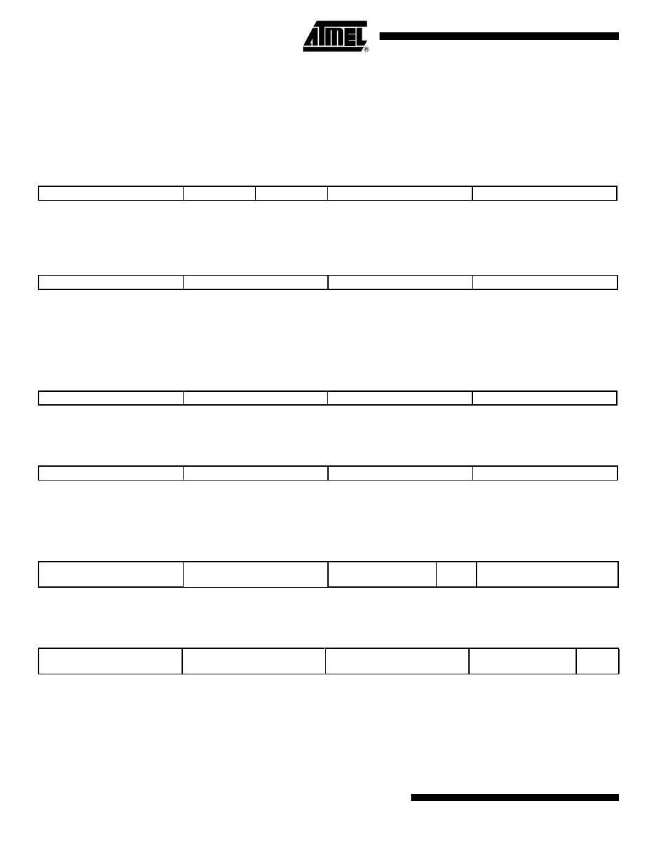
To Receive Word transfers
Data received on appropriate slot: data[19:0] = {Byte2[3:0], Byte1[7:0], Byte0[7:0]}.
Word stored in AC’97 Controller Channel x Receive Holding Register (AC97C_CxRHR)
(Received Data)
.
Data is read from AC’97 Controller Channel x Receive Holding Register (AC97C_CxRHR)
when Channel x data size is greater than 16 bits and when big-endian mode is enabled (data
written to memory).
To Receive Halfword Transfers
Data received on appropriate slot: data[19:0] = {0x0, Byte1[7:0], Byte0[7:0]}.
Halfword stored in AC’97 Controller Channel x Receive Holding Register (AC97C_CxRHR)
(Received Data).
Data is read from AC’97 Controller Channel x Receive Holding Register (AC97C_CxRHR)
when data size is equal to 16 bits and when big-endian mode is enabled.
To Receive 10-bit Samples
Data received on appropriate slot: data[19:0] = {0x000, Byte1[1:0], Byte0[7:0]}.Halfword stored
in AC’97 Controller Channel x Receive Holding Register (AC97C_CxRHR) (Received Data)
Data read from AC’97 Controller Channel x Receive Holding Register (AC97C_CxRHR) when
data size is equal to 10 bits and when big-endian mode is enabled.
37.6.3
Variable Sample Rate
The problem of variable sample rate can be summarized by a simple example. When passing
a 44.1 kHz stream across the AC-link, for every 480 audio output frames that are sent across,
441 of them must contain valid sample data. The new AC’97 standard approach calls for the
addition of “on-demand” slot request flags. The AC‘97 Codec examines its sample rate control
register, the state of its FIFOs, and the incoming SDATA_OUT tag bits (slot 0) of each output
31
24
23
20
19
16
15
8
7
0
–
–
Byte2[3:0]
Byte1[7:0]
Byte0[7:0]
31
24
23
16
15
8
7
0
Byte0[7:0]
Byte1[7:0]
{0x0, Byte2[3:0]}
0x00
31
24
23
16
15
8
7
0
–
–
Byte1[7:0]
Byte0[7:0]
31
24
23
16
15
8
7
0
–
–
Byte0[7:0]
Byte1[7:0]
31
24
23
16
15
10
9
8
7
0
–
–
–
Byte1
[1:0]
Byte0[7:0]
31
24
23
16
15
8
7
3
1
0
–
–
Byte0[7:0]
0x00
Byte1
[1:0]