Pulse width modulation (pwm) controller, 1 description, 2 block diagram – Rainbow Electronics AT91CAP9S250A User Manual
Page 739
739
6264A–CAP–21-May-07
AT91CAP9S500A/AT91CAP9S250A
40. Pulse Width Modulation (PWM) Controller
40.1
Description
The PWM macrocell controls several channels independently. Each channel controls one
square output waveform. Characteristics of the output waveform such as period, duty-cycle
and polarity are configurable through the user interface. Each channel selects and uses one of
the clocks provided by the clock generator. The clock generator provides several clocks result-
ing from the division of the PWM macrocell master clock.
All PWM macrocell accesses are made through APB mapped registers.
Channels can be synchronized, to generate non overlapped waveforms. All channels integrate
a double buffering system in order to
prevent
an unexpected output waveform while modifying
the period or the duty-cycle.
40.2
Block Diagram
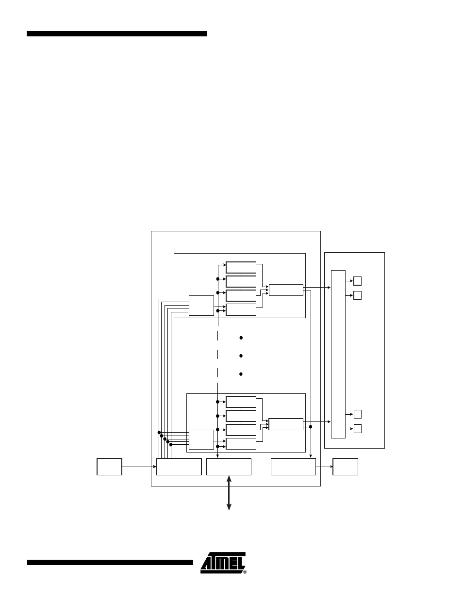
Figure 40-1. Pulse Width Modulation Controller Block Diagram
PWM
Controller
APB
PWMx
PWMx
PWMx
Channel
Update
Duty Cycle
Counter
PWM0
Channel
PIO
AIC
PMC
MCK
Clock Generator
APB Interface
Interrupt Generator
Clock
Selector
Period
Comparator
Update
Duty Cycle
Counter
Clock
Selector
Period
Comparator
PWM0
PWM0