Rainbow Electronics AT91CAP9S250A User Manual
Page 626
626
6264A–CAP–21-May-07
AT91CAP9S500A/AT91CAP9S250A
Th e ap plication can also wait for an interru pt no tice in order to re ad d ata from
AC97C_CxRHR. The interrupt remains active until RXRDY is cleared by reading
AC97C_CxSR.
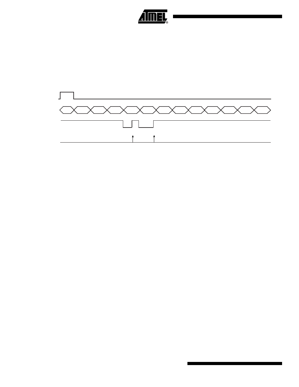
The RXRDY flag in AC97C_CxSR is set automatically when data is received in the Channel x
shift register. Data is then shifted to AC97C_CxRHR.
Figure 37-6. Audio Transfer (PCM L Front, PCM R Front) on Channel x
If the previously received data has not been read by the application, the new data overwrites
the data already waiting in AC97C_CxRHR, therefore the OVRUN flag in AC97C_CxSR is
raised. The application can either poll the OVRUN flag in AC97C_CxSR or wait for an interrupt
notice. The interrupt remains active until the OVRUN flag in AC97C_CxSR is set.
The AC’97 Controller can also be used in sound recording devices in association with an
AC97 Codec. The AC‘97 Controller may also be exposed to heavy PCM transfers. The appli-
cation can usethe PDC connected to channel A in order to reduce processor overhead and
increase performance especially under an operating system.
The PDC receive counter values must be equal to the number of PCM samples to be received,
each sample goes in one slot.
37.6.2.5
AC‘97 Input Frame
The AC’97 Controller receives a thirteen slot frame on the AC-Link sent by the AC97 Codec.
The first slot (tag slot or slot 0) flags the validity of the entire frame and the validity of each slot;
whether a slot carries valid data or not. Slots 1 and 2 are used if the application requires status
informations from AC97 Codec. Slots [3:12] are used according to AC’97 Controller Output
Channel Assignment Register (AC97C_ICA) content. The AC’97 Controller will not receive
any data from any slot if AC97C_ICA is not assigned to a channel in input.
37.6.2.6
Configuring and Using Interrupts
Instead of polling flags in AC’97 Controller Global Status Register (AC97C_SR) and in AC’97
Controller Channel x Status Register (AC97C_CxSR), the application can wait for an interrupt
notice. The following steps show how to configure and use interrupts correctly:
• Set the interruptible flag in AC’97 Controller Channel x Mode Register (AC97C_CxMR).
• Set the interruptible event and channel event in AC’97 Controller Interrupt Enable Register
(AC97C_IER).
The interrupt handler must read both AC’97 Controller Global Status Register (AC97C_SR)
and AC’97 Controller Interrupt Mask Register (AC97C_IMR) and AND them to get the real
interrupt source. Furthermore, to get which event was activated, the interrupt handler has to
Slot #
AC97FS
0
1
2
3
4
5
6
7
8
9
10
11
12
RXRDYCx
(AC97C_SR)
Read access to
AC97C_RHRx
AC97RX
(Codec output)
TAG
STATUS
ADDR
STATUS
DATA
PCM
LEFT
PCM
RIGHT
LINE 1
DAC
PCM
MIC
RSVED
RSVED
RSVED
LINE 2
ADC
HSET
ADC
IO
STATUS