2 block diagram, Figure 26-1. dma controller (dmac) block diagram – Rainbow Electronics AT91CAP9S250A User Manual
Page 278
278
6264A–CAP–21-May-07
AT91CAP9S500A/AT91CAP9S250A
26.2
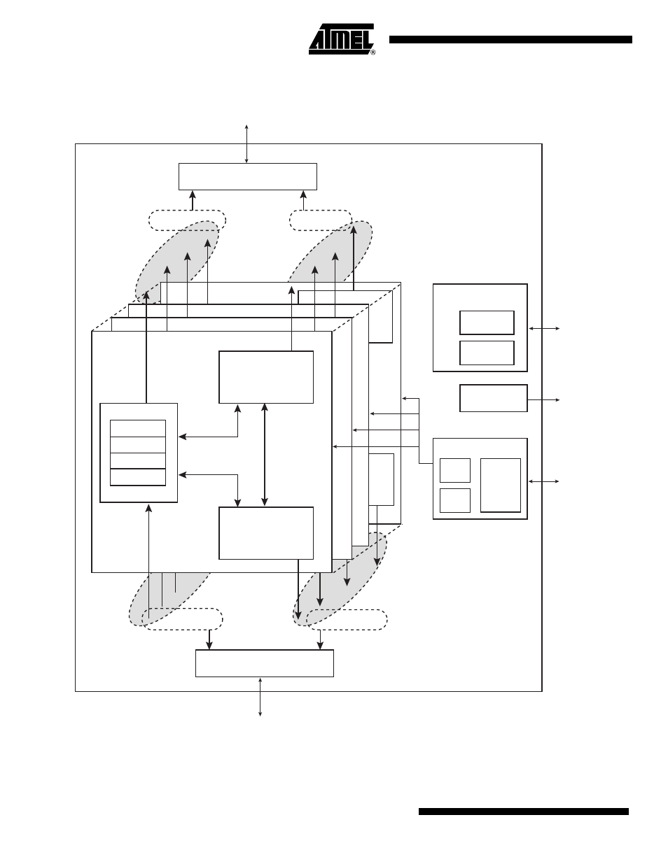
Block Diagram
Figure 26-1. DMA Controller (DMAC) Block Diagram
DMA Destination
DMA Channel 0
DMA Destination
Control State Machine
Destination Pointer
Management
DMA Source
Control State Machine
Source Pointer
Management
DMA FIFO Controller
DMA FIFO
Up to 64 bytes
DMA Channel 0
Read data path
from source
DMA Channel 0
Write data path
to destination
DMA Channel 1
DMA Channel 2
DMA Channel n
External
Triggers
Soft
Triggers
DMA
REQ/ACK
Interface
Trigger Manager
DMA Interrupt
Controller
Status
Registers
Configuration
Registers
Atmel APB rev2 Interface
DMA AHB Lite Master Interface 0
DMA AHB Lite Master Interface 1
DMA Global Control
and Data Mux
DMA Global
Request Arbiter
DMA Global Control
and Data Mux
DMA Global
Request Arbiter
DMA Destination
Requests Pool
DMA Write
Datapath Bundles
DMA Source
Requests Pool
DMA Read
Datapath Bundles
DMA
Atmel
APB
Interface
DMA Interrupt
DMA
Hardware
Handshaking
Interface
AMBA AHB Layer 0
AMBA AHB Layer 1