Rainbow Electronics AT91CAP9S250A User Manual
Page 689
689
6264A–CAP–21-May-07
AT91CAP9S500A/AT91CAP9S250A
The SAMPLE POINT is the point in time at which the bus level is read and interpreted as the
value of that respective bit. Its location is at the end of PHASE_SEG1.
SJW: ReSynchronization Jump Width.
The ReSynchronization Jump Width defines the limit to the amount of lengthening or shorten-
ing of the Phase Segments.
SJW is programmable to be the minimum of PHASE SEG1 and 4 TQ.
If the SMP field in the CAN_BR register is set, then the incoming bit stream is sampled three
times with a period of half a CAN clock period, centered on sample point.
In the CAN controller, the length of a bit on the CAN bus is determined by the parameters
(BRP, PROPAG, PHASE1 and PHASE2).
The time quantum is calculated as follows:
Note: The BRP field must be within the range [1, 0x7F], i.e., BRP = 0 is not authorized.
To compensate for phase shifts between clock oscillators of different controllers on the bus,
the CAN controller must resynchronize on any relevant signal edge of the current transmis-
sion. The resynchronization shortens or lengthens the bit time so that the position of the
sample point is shifted with regard to the detected edge. The resynchronization jump width
(SJW) defines the maximum of time by which a bit period may be shortened or lengthened by
resynchronization.
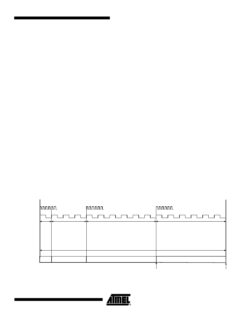
Figure 39-5. CAN Bit Timing
Example of bit timing determination for CAN baudrate of 500 Kbit/s:
MCK = 48MHz
t
BIT
t
CSC
t
PRS
t
PHS1
t
PHS2
+
+
+
=
t
CSC
BRP
1
+
(
)
MCK
⁄
=
t
PRS
t
CSC
PROPAG
1
+
(
)
×
=
t
PHS1
t
CSC
PHASE1
1
+
(
)
×
=
t
PHS2
t
CSC
PHASE2
1
+
(
)
×
=
t
SJW
t
CSC
SJW
1
+
(
)
×
=
SYNC_
SEG
PROP_SEG
PHASE_SEG1
PHASE_SEG2
NOMINAL BIT TIME
Sample Point
Transmission Point
MCK
CAN Clock
t
CSC
t
PRS
t
PHS1
t
PHS2