7 master mode, 1 definition, 2 application block diagram – Rainbow Electronics AT91CAP9S250A User Manual
Page 487: 3 programming master mode, 4 master transmitter mode
487
6264A–CAP–21-May-07
AT91CAP9S500A/AT91CAP9S250A
34.7
Master Mode
34.7.1
Definition
The Master is the device which starts a transfer, generates a clock and stops it.
34.7.2
Application Block Diagram
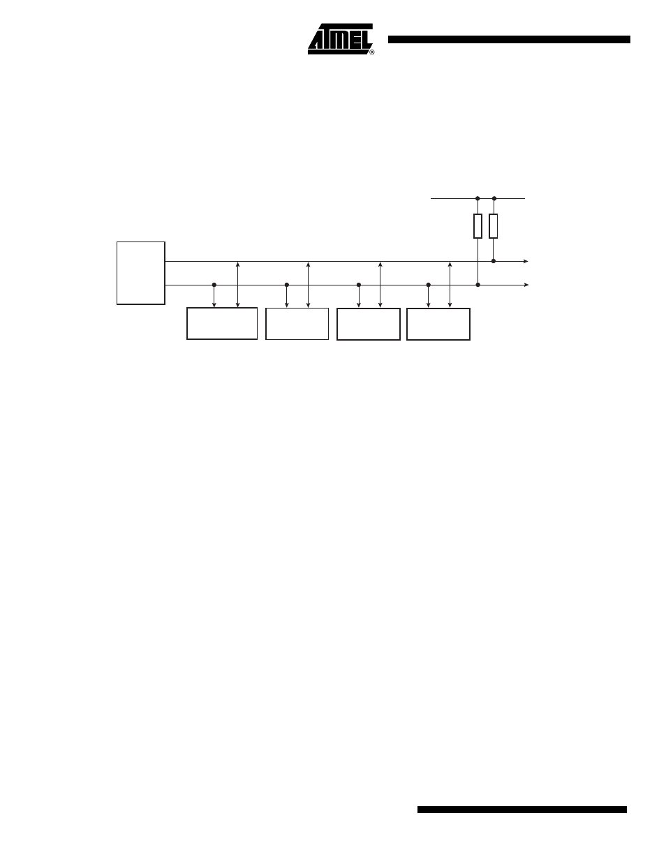
Figure 34-5. Master Mode Typical Application Block Diagram
34.7.3
Programming Master Mode
The following registers have to be programmed before entering Master mode:
1.
DADR (+ IADRSZ + IADR if a 10 bit device is addressed): The device address is used
to access slave devices in read or write mode.
2.
CKDIV + CHDIV + CLDIV: Clock Waveform.
3.
SVDIS: Disable the slave mode.
4.
MSEN: Enable the master mode.
34.7.4
Master Transmitter Mode
After the master initiates a Start condition when writing into the Transmit Holding Register,
TWI_THR, it sends a 7-bit slave address, configured in the Master Mode register (DADR in
TWI_MMR), to notify the slave device. The bit following the slave address indicates the transfer
direction, 0 in this case (MREAD = 0 in TWI_MMR).
The TWI transfers require the slave to acknowledge each received byte. During the acknowl-
edge clock pulse (9th pulse), the master releases the data line (HIGH), enabling the slave to pull
it down in order to generate the acknowledge. The master polls the data line during this clock
pulse and sets the Not Acknowledge bit (NACK) in the status register if the slave does not
acknowledge the byte. As with the other status bits, an interrupt can be generated if enabled in
the interrupt enable register (TWI_IER). If the slave acknowledges the byte, the data written in
the TWI_THR, is then shifted in the internal shifter and transferred. When an acknowledge is
detected, the TXRDY bit is set until a new write in the TWI_THR. When no more data is written
into the TWI_THR, the master generates a stop condition to end the transfer. The end of the
complete transfer is marked by the TWI_TXCOMP bit set to one. See
and
.
Host with
TWI
Interface
TWD
TWCK
Atmel TWI
Serial EEPROM
I²C RTC
I²C LCD
Controller
Slave 1
Slave 2
Slave 3
VDD
I²C Temp.
Sensor
Slave 4
Rp: Pull up value as given by the I²C Standard
Rp
Rp