6 implementation examples, 1 16-bit sdram – Rainbow Electronics AT91CAP9S250A User Manual
Page 157
157
6264A–CAP–21-May-07
AT91CAP9S500A/AT91CAP9S250A
21.6
Implementation Examples
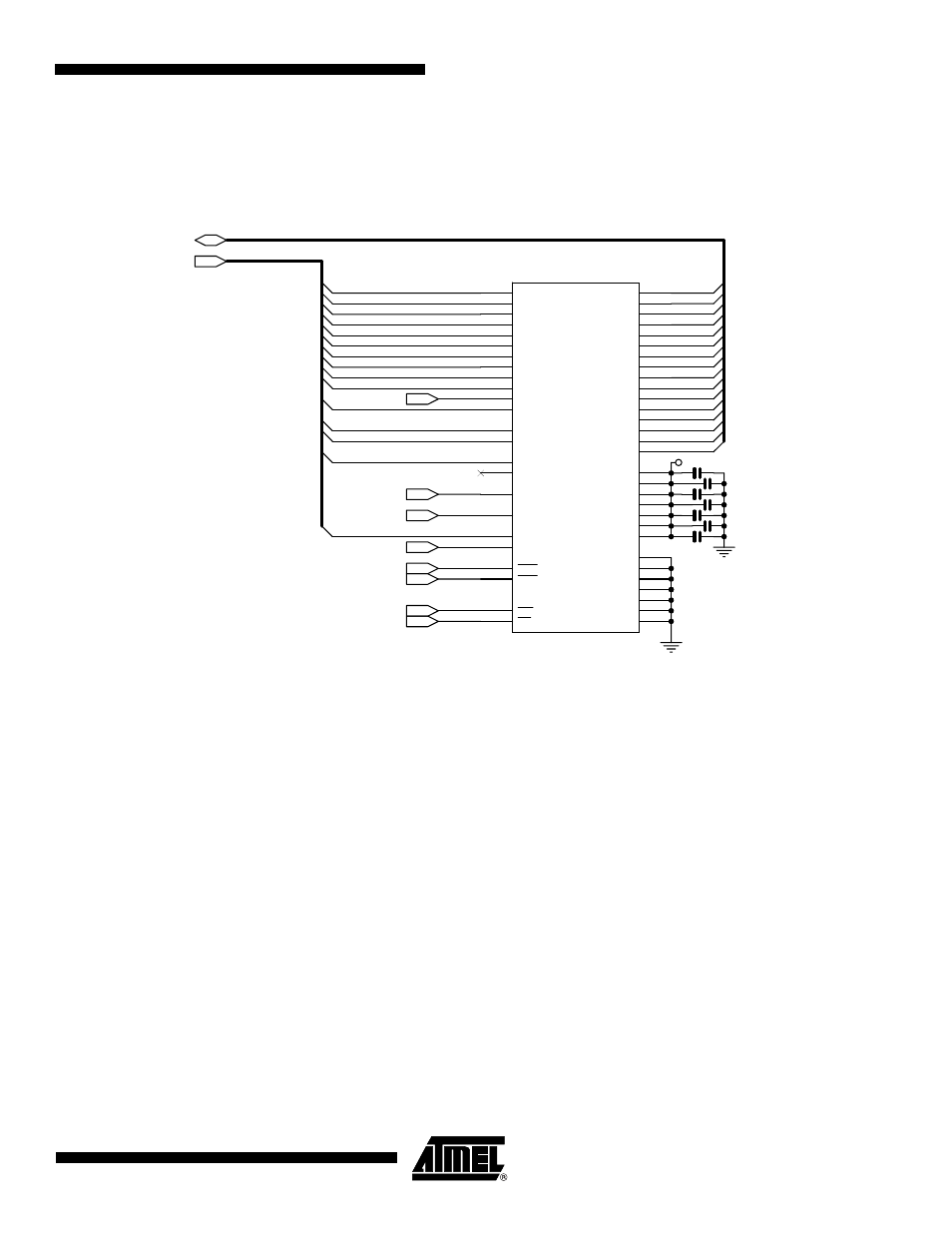
21.6.1
16-bit SDRAM
21.6.1.1
Hardware Configuration
21.6.1.2
Software Configuration
The following configuration has to be performed:
• Assign the EBI CS1 to the SDRAM controller by setting the bit EBI_CS1A in the EBI Chip
Select Assignment Register located in the bus matrix memory space.
• Initialize the SDRAM Controller depending on the SDRAM device and system bus
frequency.
The Data Bus Width is to be programmed to 16 bits.
The SDRAM initialization sequence is described in the “SDRAM device initialisation” part of
the SDRAM controller.
A10
A11
D4
A13
A0
D2
A8
A16
D10
A17
D5
D12
A6
A3
D9
D14
D15
A14
D3
A9
D0
A5
D6
D7
A2
SDA10
D8
D1
A4
D13
D11
A7
RAS
CAS
SDA10
SDWE
SDCKE
SDCK
NBS1
SDDRCS
D[0..15]
A[0..17]
3V3
(NBS0)
(Not used A1, A12, A15)
C1
100NF
C1
100NF
C3
100NF
C3
100NF
C7
100NF
C7
100NF
C6
100NF
C6
100NF
C4
100NF
C4
100NF
C2
100NF
C2
100NF
U1
U1
A0
23
A1
24
A2
25
A3
26
A4
29
A5
30
A6
31
A7
32
A8
33
A9
34
A10
22
BA0
20
A12
36
DQ0
2
DQ1
4
DQ2
5
DQ3
7
DQ4
8
DQ5
10
DQ6
11
DQ7
13
DQ8
42
DQ9
44
DQ10
45
DQ11
47
DQ12
48
DQ13
50
DQ14
51
DQ15
53
VDD
1
VSS
28
VSS
41
VDDQ
3
VDD
27
N.C
40
CLK
38
CKE
37
DQML
15
DQMH
39
CAS
17
RAS
18
WE
16
CS
19
VDDQ
9
VDDQ
43
VDDQ
49
VSSQ
6
VSSQ
12
VSSQ
46
VSSQ
52
VDD
14
VSS
54
A11
35
BA1
21
C5
100NF
C5
100NF