1 main oscillator connections, 2 main oscillator startup time, 3 main oscillator control – Rainbow Electronics AT91CAP9S250A User Manual
Page 350
350
6264A–CAP–21-May-07
AT91CAP9S500A/AT91CAP9S250A
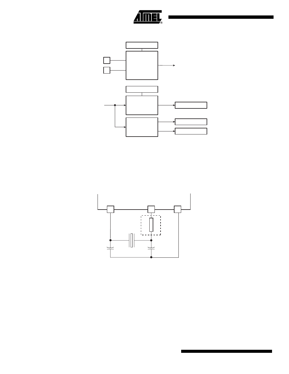
Figure 28-2. Main Oscillator Block Diagram
28.3.1
Main Oscillator Connections
The Clock Generator integrates a Main Oscillator that is designed for a 8 to 16 MHz fundamental
crystal. The typical crystal connection is illustrated in
. For further details on the elec-
trical characteristics of the Main Oscillator, see the section “DC Characteristics” of the product
datasheet.
Figure 28-3. Typical Crystal Connection
28.3.2
Main Oscillator Startup Time
The startup time of the Main Oscillator is given in the DC Characteristics section of the product
datasheet. The startup time depends on the crystal frequency and decreases when the fre-
quency rises.
28.3.3
Main Oscillator Control
To minimize the power required to start up the system, the main oscillator is disabled after reset
and slow clock is selected.
The software enables or disables the main oscillator so as to reduce power consumption by
clearing the MOSCEN bit in the Main Oscillator Register (CKGR_MOR).
XIN
XOUT
MOSCEN
Main
Oscillator
Counter
OSCOUNT
MOSCS
MAINCK
Main Clock
Main Clock
Frequency
Counter
MAINF
MAINRDY
SLCK
Slow Clock
Main
Oscillator
1K
XIN
XOUT
GND
AT91 Microcontroller