2 spi mode register – Rainbow Electronics AT91CAP9S250A User Manual
Page 472
472
6264A–CAP–21-May-07
AT91CAP9S500A/AT91CAP9S250A
33.7.2
SPI Mode Register
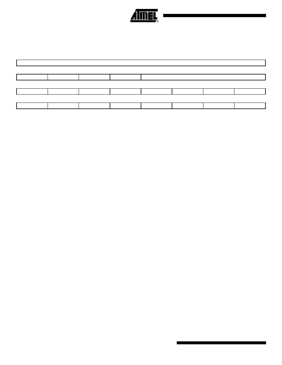
Name: SPI_MR
Access Type: Read/Write
• MSTR: Master/Slave Mode
0 = SPI is in Slave mode.
1 = SPI is in Master mode.
• PS: Peripheral Select
0 = Fixed Peripheral Select.
1 = Variable Peripheral Select.
• PCSDEC: Chip Select Decode
0 = The chip selects are directly connected to a peripheral device.
1 = The four chip select lines are connected to a 4- to 16-bit decoder.
When PCSDEC equals one, up to 15 Chip Select signals can be generated with the four lines using an external 4- to 16-bit
decoder. The Chip Select Registers define the characteristics of the 15 chip selects according to the following rules:
SPI_CSR0 defines peripheral chip select signals 0 to 3.
SPI_CSR1 defines peripheral chip select signals 4 to 7.
SPI_CSR2 defines peripheral chip select signals 8 to 11.
SPI_CSR3 defines peripheral chip select signals 12 to 14.
• MODFDIS: Mode Fault Detection
0 = Mode fault detection is enabled.
1 = Mode fault detection is disabled.
• LLB: Local Loopback Enable
0 = Local loopback path disabled.
1 = Local loopback path enabled (
LLB controls the local loopback on the data serializer for testing in Master Mode only. (MISO is internally connected on
MOSI.)
• PCS: Peripheral Chip Select
This field is only used if Fixed Peripheral Select is active (PS = 0).
If PCSDEC = 0:
PCS = xxx0
NPCS[3:0] = 1110
PCS = xx01
NPCS[3:0] = 1101
PCS = x011
NPCS[3:0] = 1011
PCS = 0111
NPCS[3:0] = 0111
PCS = 1111
forbidden (no peripheral is selected)
(x = don’t care)
31
30
29
28
27
26
25
24
DLYBCS
23
22
21
20
19
18
17
16
–
–
–
–
PCS
15
14
13
12
11
10
9
8
–
–
–
–
–
–
–
–
7
6
5
4
3
2
1
0
LLB
–
–
MODFDIS
PCSDEC
PS
MSTR