Rainbow Electronics AT91CAP9S250A User Manual
Page 852
852
6264A–CAP–21-May-07
AT91CAP9S500A/AT91CAP9S250A
+ NB_BANK_EPT1 x SIZE_EPT1
+ NB_BANK_EPT2 x SIZE_EPT2
+ NB_BANK_EPT3 x SIZE_EPT3
+ NB_BANK_EPT4 x SIZE_EPT4
+ NB_BANK_EPT5 x SIZE_EPT5
+ NB_BANK_EPT6 x SIZE_EPT6
+... (refer to
44.5.8 UDPHS Endpoint Configuration Register
)
If a user tries to configure endpoints with a size the sum of which is greater than the DPRAM,
then the EPT_MAPD is not set.
The application has access to the physical block of DPR reserved for the endpoint through a
64
KB logical address space.
The physical block of DPR allocated for the endpoint is remapped all along the
64
KB logical
address space. The application can write a
64
KB buffer linearly.
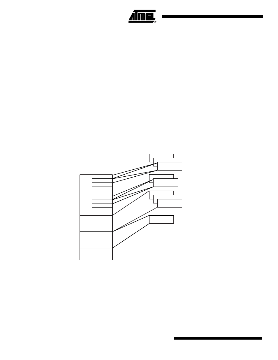
Figure 44-4. Logical Address Space for DPR Access:
Configuration examples of UDPHS_EPTCTLx (
UDPHS Endpoint Control Register
) for Bulk IN
endpoint type follow below.
• With DMA
– AUTO_VALID: Automatically validate the packet and switch to the next bank.
– EPT_ENABL: Enable endpoint.
• Without DMA:
– TX_BK_RDY: An interrupt is generated after each transmission.
64 KB
EP0
64 KB
EP1
64 KB
EP2
DPR
Logical address
8 to 64 B
8 to1024 B
8 to1024 B
8 to1024 B
64 KB
EP3
...
8 to 64 B
8 to 64 B
8 to 64 B
...
...
x banks
y banks
z banks
8 to1024 B
8 to1024 B
8 to1024 B