Error corrected code (ecc) controller, 1 description, 2 block diagram – Rainbow Electronics AT91CAP9S250A User Manual
Page 267: 3 functional description
267
6264A–CAP–21-May-07
AT91CAP9S500A/AT91CAP9S250A
25. Error Corrected Code (ECC) Controller
25.1
Description
NAND Flash/SmartMedia devices contain by default invalid blocks which have one or more
invalid bits. Over the NAND Flash/SmartMedia lifetime, additional invalid blocks may occur
which can be detected/corrected by ECC code.
The ECC Controller is a mechanism that encodes data in a manner that makes possible the
identification and correction of certain errors in data. The ECC controller is capable of single bit
error correction and 2-bit random detection. When NAND Flash/SmartMedia have more than 2
bits of errors, the data cannot be corrected.
The ECC user interface is compliant with the ARM Advanced Peripheral Bus (APB rev2).
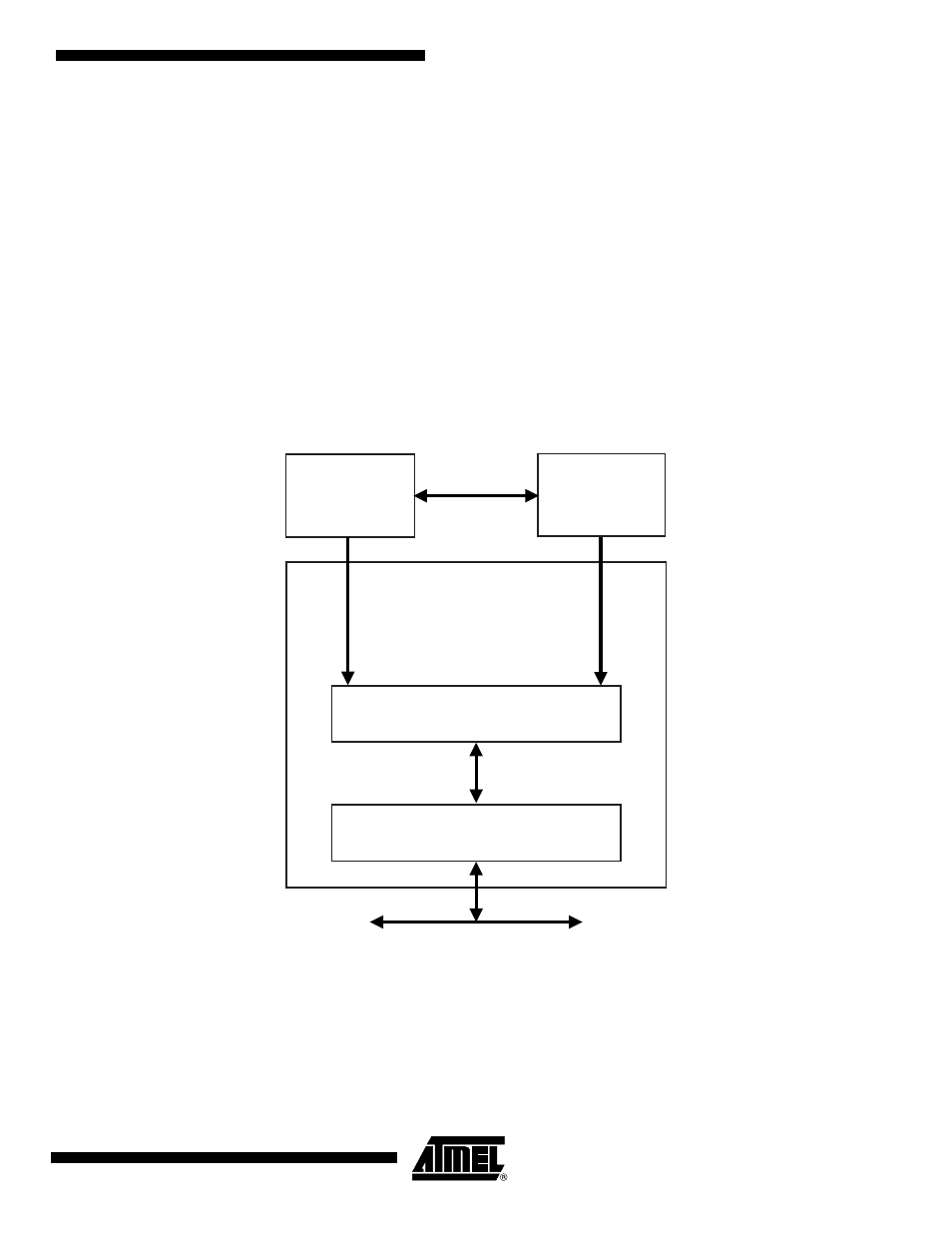
25.2
Block Diagram
Figure 25-1. Block Diagram
25.3
Functional Description
A page in NAND Flash and SmartMedia memories contains an area for main data and an addi-
tional area used for redundancy (ECC). The page is organized in 8-bit or 16-bit words. The page
size corresponds to the number of words in the main area plus the number of words in the extra
area used for redundancy.
User Interface
Ctrl/ECC Algorithm
Static
Memory
Controller
APB
NAND Flash
SmartMedia
Logic
ECC
Controller