Rainbow Electronics AT91CAP9S250A User Manual
Page 297
297
6264A–CAP–21-May-07
AT91CAP9S500A/AT91CAP9S250A
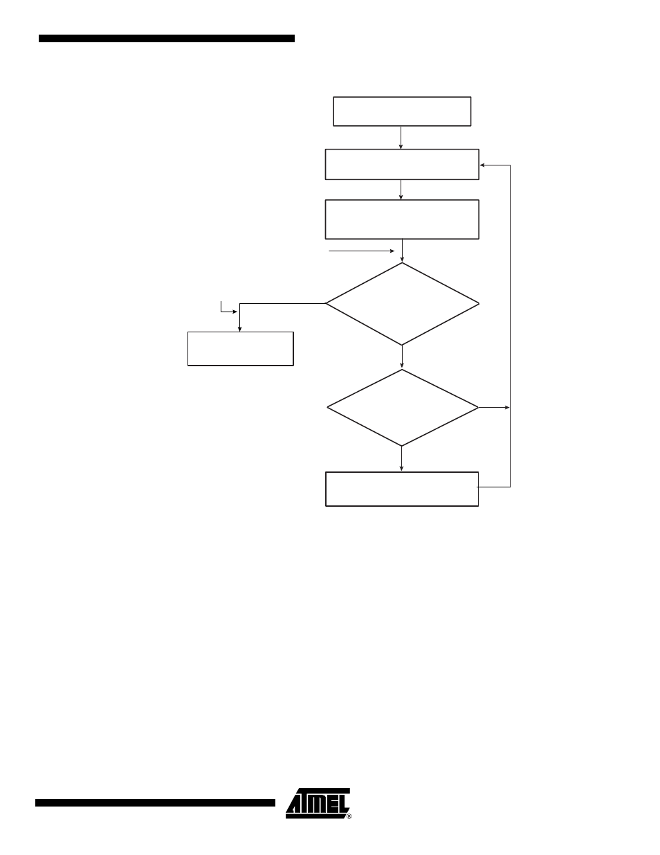
Figure 26-11. DMAC Transfer Flow for Source and Destination Address Auto-reloaded
26.3.5.5
Multi-buffer Transfer with Source Address Auto-reloaded and Linked List Destination Address (Row 6)
1.
Read the Channel Enable register to choose a free (disabled) channel.
2.
Set up the chain of linked list items (otherwise known as buffer descriptors) in memory.
Write the control information in the LLI.DMAC_CTRLAx and DMAC_CTRLBx registers
location of the buffer descriptor for each LLI in memory for channel x. For example, in
the register you can program the following:
a.
Set up the transfer type (memory or non-memory peripheral for source and desti-
nation) and flow control peripheral by programming the FC of the DMAC_CTRLBx
register.
b.
Set up the transfer characteristics, such as:
– i. Transfer width for the source in the SRC_WIDTH field.
– ii. Transfer width for the destination in the DST_WIDTH field.
– iii. Source AHB master interface layer in the SIF field where source resides.
– iv. Destination AHB master interface layer in the DIF field where destination resides.
– v. Incrementing/decrementing or fixed address for source in SRC_INCR field.
– vi. Incrementing/decrementing or fixed address for destination DST_INCR field.
Channel Enabled by
software
Buffer Transfer
Replay mode for SADDRx,
DADDRx, CTRLAx, CTRLBx
Channel Disabled by
hardware
Buffer Complete interrupt
generated here
HDMA Transfer Complete
Interrupt generated here
yes
no
yes
Stall until STALLED is cleared
by writing to KEEPON field
EBCIMR[x]=1?
no
Is HDMA in Row1 of
HDMA State Machine table?