14 ac’97 controller channel c mode register – Rainbow Electronics AT91CAP9S250A User Manual
Page 640
640
6264A–CAP–21-May-07
AT91CAP9S500A/AT91CAP9S250A
37.7.14
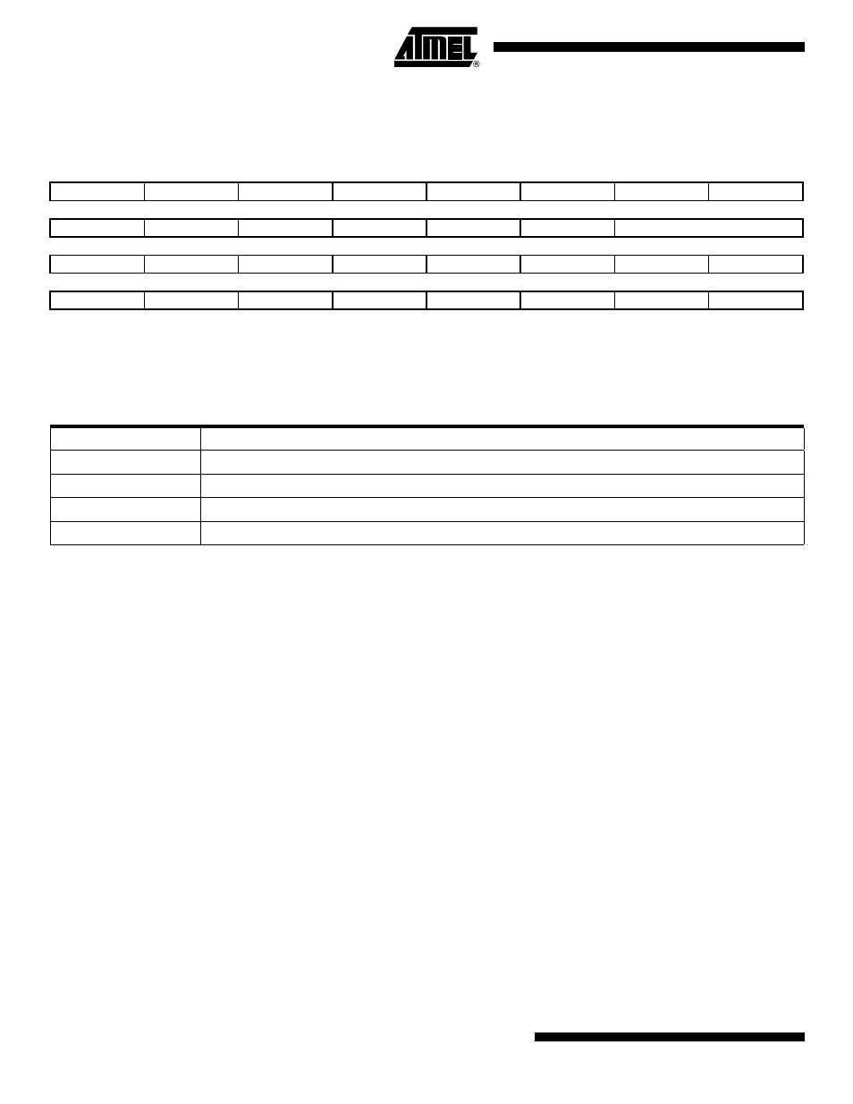
AC’97 Controller Channel C Mode Register
Register Name:
AC97C_CCMR
Access Type:
Read/Write
• CEM: Channel x Endian Mode
0: Transferring Data through Channel x is straight forward (Little-Endian).
1: Transferring Data through Channel x from/to a memory is performed with from/to Big-Endian format translation.
• SIZE: Channel x Data Size
SIZE Encoding
Note:
Each time slot in the data phase is 20 bit long. For example, if a 16-bit sample stream is being played to an AC 97 DAC, the first
16 bit positions are presented to the DAC MSB-justified. They are followed by the next four bit positions that the AC’97 Controller
fills with zeroes. This process ensures that the least significant bits do not introduce any DC biasing, regardless of the imple-
mented DAC’s resolution (16-, 18-, or 20-bit).
• CEN: Channel x Enable
0: Data transfer is disabled on Channel x.
1: Data transfer is enabled on Channel x.
• PDCCEN: Peripheral Data Controller Channel Enable
0: Channel x is not transferred through a Peripheral Data Controller Channel. Related PDC flags are ignored or not
generated.
1: Channel x is transferred through a Peripheral Data Controller Channel. Related PDC flags are taken into account or
generated.
31
30
29
28
27
26
25
24
–
–
–
–
–
–
–
–
23
22
21
20
19
18
17
16
–
–
CEN
–
–
CEM
SIZE
15
14
13
12
11
10
9
8
–
–
–
–
–
–
–
–
7
6
5
4
3
2
1
0
–
–
OVRUN
RXRDY
–
UNRUN
TXEMPTY
TXRDY
SIZE
Selected Channel
0x0
20 bits
0x1
18bits
0x2
16 bits
0x3
10 bits