Timer counter (tc), 1 description – Rainbow Electronics AT91CAP9S250A User Manual
Page 647
647
6264A–CAP–21-May-07
AT91CAP9S500A/AT91CAP9S250A
38. Timer Counter (TC)
38.1
Description
The Timer Counter (TC) includes three identical 16-bit Timer Counter channels.
Each channel can be independently programmed to perform a wide range of functions including
frequency measurement, event counting, interval measurement, pulse generation, delay timing
and pulse width modulation.
Each channel has three external clock inputs, five internal clock inputs and two multi-purpose
input/output signals which can be configured by the user. Each channel drives an internal inter-
rupt signal which can be programmed to generate processor interrupts.
The Timer Counter block has two global registers which act upon all three TC channels.
The Block Control Register allows the three channels to be started simultaneously with the same
instruction.
The Block Mode Register defines the external clock inputs for each channel, allowing them to be
chained.
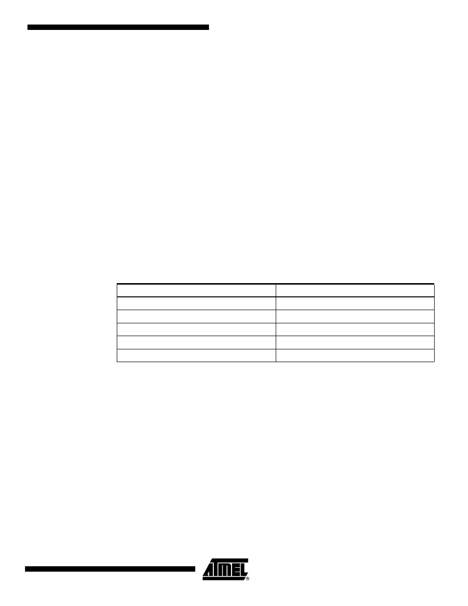
gives the assignment of the device Timer Counter clock inputs common to Timer
Counter 0 to 2
Table 38-1.
Timer Counter Clock Assignment
Name
Definition
TIMER_CLOCK1
MCK/2
TIMER_CLOCK2
MCK/8
TIMER_CLOCK3
MCK/32
TIMER_CLOCK4
MCK/128
TIMER_CLOCK5
SCLK