3 clocks – Rainbow Electronics AT91CAP9S250A User Manual
Page 915
915
6264A–CAP–21-May-07
AT91CAP9S500A/AT91CAP9S250A
The RGB 5:6:5 input format is processed to be displayed as RGB 5:5:5 format, compliant with
the 16-bit mode of the LCD controller.
45.3.3
Clocks
The sensor master clock (ISI_MCK) can be generated either by the Advanced Power Manage-
ment Controller (APMC) through a Programmable Clock output or by an external oscillator
connected to the sensor.
None of the sensors embeds a power management controller, so providing the clock by the
APMC is a simple and efficient way to control power consumption of the system.
Care must be taken when programming the system clock. The ISI has two clock domains, the
system bus clock and the pixel clock provided by sensor. The two clock domains are not syn-
chronized, but the system clock must be faster than pixel clock.
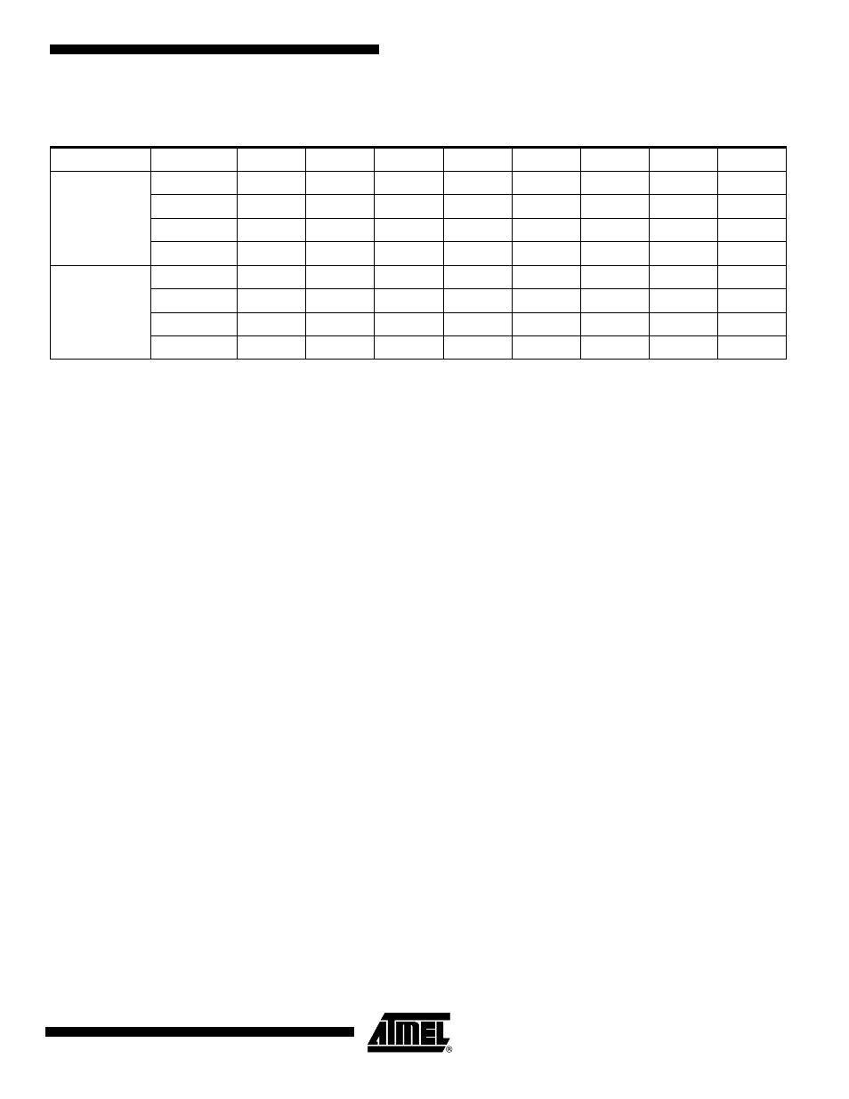
Table 45-5.
RGB Format in Default Mode, RGB_CFG = 00, Swap Activated
Mode
Byte
D7
D6
D5
D4
D3
D2
D1
D0
RGB 8:8:8
Byte 0
R0(i)
R1(i)
R2(i)
R3(i)
R4(i)
R5(i)
R6(i)
R7(i)
Byte 1
G0(i)
G1(i)
G2(i)
G3(i)
G4(i)
G5(i)
G6(i)
G7(i)
Byte 2
B0(i)
B1(i)
B2(i)
B3(i)
B4(i)
B5(i)
B6(i)
B7(i)
Byte 3
R0(i+1)
R1(i+1)
R2(i+1)
R3(i+1)
R4(i+1)
R5(i+1)
R6(i+1)
R7(i+1)
RGB 5:6:5
Byte 0
G3(i)
G4(i)
G5(i)
R0(i)
R1(i)
R2(i)
R3(i)
R4(i)
Byte 1
B0(i)
B1(i)
B2(i)
B3(i)
B4(i)
G0(i)
G1(i)
G2(i)
Byte 2
G3(i+1)
G4(i+1)
G5(i+1)
R0(i+1)
R1(i+1)
R2(i+1)
R3(i+1)
R4(i+1)
Byte 3
B0(i+1)
B1(i+1)
B2(i+1)
B3(i+1)
B4(i+1)
G0(i+1)
G1(i+1)
G2(i+1)