3 matrix masters, 4 matrix slaves – Rainbow Electronics AT91CAP9S250A User Manual
Page 17
17
6264A–CAP–21-May-07
AT91CAP9S500A/AT91CAP9S250A
– Round-Robin Arbitration, either with no default master, last accessed default master
or fixed default master
• Burst Management
– Breaking with Slot Cycle Limit Support
– Undefined Burst Length Support
• One Address Decoder provided per Master
– Three different slaves may be assigned to each decoded memory area: one for
internal boot, one for external boot, one after remap
• Boot Mode Select
– Non-volatile Boot Memory can be internal or external
– Selection is made by BMS pin sampled at reset
• Remap Command
– Allows Remapping of an Internal SRAM in Place of the Boot Non-Volatile Memory
– Allows Handling of Dynamic Exception Vectors
7.3
Matrix Masters
The Bus Matrix of the AT91CAP9S500A/AT91CAP9S250A manages twelve Masters and thus
each master can perform an access concurrently with the others, assuming that the slave it
accesses is available.
Each Master has its own decoder, which is defined specifically for each master. In order to sim-
plify the addressing, all the masters have the same decoding.
7.4
Matrix Slaves
The Bus Matrix of the AT91CAP9S500A/AT91CAP9S250A manages ten Slaves. Each Slave
has its own arbiter, thus permitting a different arbitration per Slave to be programmed.
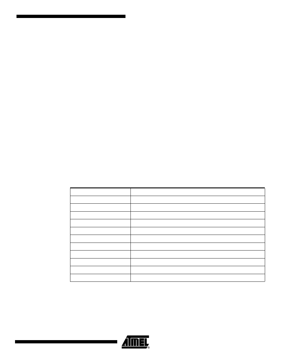
Table 7-1.
List of Bus Matrix Masters
Master 0
ARM926
™
Instruction
Master 1
ARM926 Data
Master 2
Peripheral DMA Controller
Master 3
LCD Controller
Master 4
USB High Speed Device Controller
Master 5
Image Sensor Interface
Master 6
DMA Controller
Master 7
Ethernet MAC
Master 8
OHCI USB Host Controller
Master 9
MP Block Master 0
Master 10
MP Block Master 1
Master 11
MP Block Master 2