Figure 35-18, Figure 35-19 – Rainbow Electronics AT91CAP9S250A User Manual
Page 542
542
6264A–CAP–21-May-07
AT91CAP9S500A/AT91CAP9S250A
switches to receiving mode. The demodulated stream is sent to the Manchester decoder.
Because of bit checking inside RF IC, the data transferred to the microcontroller is reduced by a
user-defined number of bits. The Manchester preamble length is to be defined in accordance
with the RF IC configuration.
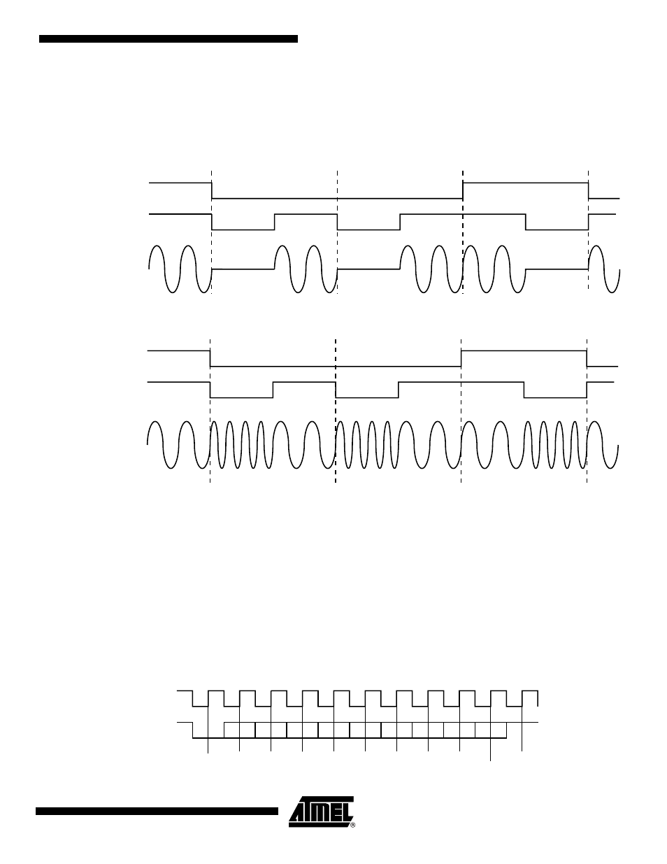
Figure 35-18. ASK Modulator Output
Figure 35-19. FSK Modulator Output
35.6.3.6
Synchronous Receiver
In synchronous mode (SYNC = 1), the receiver samples the RXD signal on each rising edge of
the Baud Rate Clock. If a low level is detected, it is considered as a start. All data bits, the parity
bit and the stop bits are sampled and the receiver waits for the next start bit. Synchronous mode
operations provide a high speed transfer capability.
Configuration fields and bits are the same as in asynchronous mode.
illustrates a character reception in synchronous mode.
Figure 35-20. Synchronous Mode Character Reception
Manchester
encoded
data
default polarity
unipolar output
Txd
ASK Modulator
Output
Uptstream Frequency F0
NRZ stream
1
0
0
1
Manchester
encoded
data
default polarity
unipolar output
Txd
FSK Modulator
Output
Uptstream Frequencies
[F0, F0+offset]
NRZ stream
1
0
0
1
D0
D1
D2
D3
D4
D5
D6
D7
RXD
Start
Sampling
Parity Bit
Stop Bit
Example: 8-bit, Parity Enabled 1 Stop
Baud Rate
Clock