Rainbow Electronics AT91CAP9S250A User Manual
Page 153
153
6264A–CAP–21-May-07
AT91CAP9S500A/AT91CAP9S250A
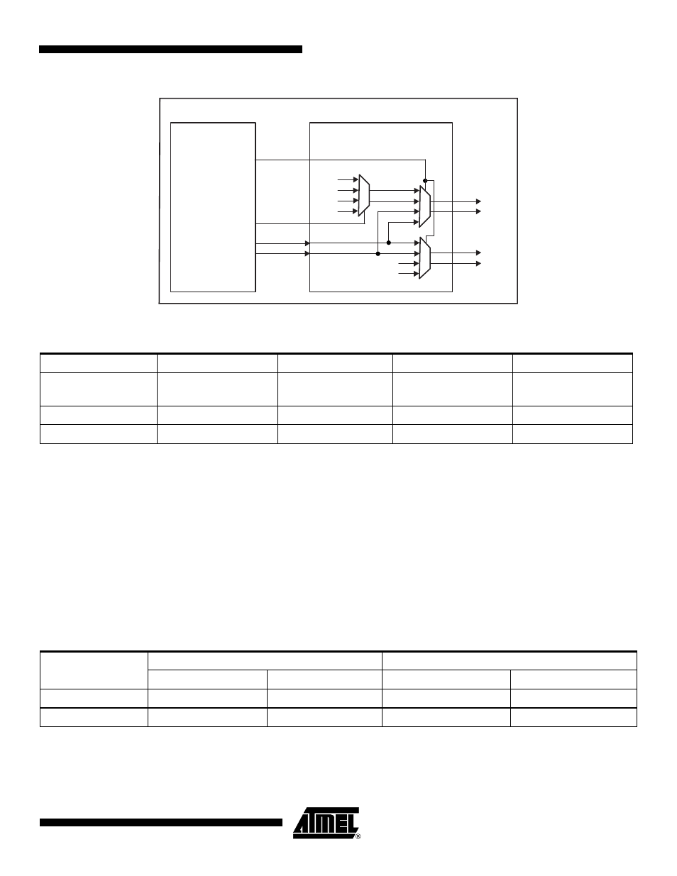
Figure 21-3. CompactFlash Read/Write Control Signals
21.5.8.4
Multiplexing of CompactFlash Signals on EBI Pins
and
illustrate the multiplexing of the Com-
pactFlash logic signals with other EBI signals on the EBI pins. The EBI pins in
are
strictly dedicated to the CompactFlash interface as soon as the EBI_CS4A and/or EBI_CS5A
field of the EBI_CSA Register
in the Chip Configuration User Interface is set. These pins must
not be used to drive any other memory devices.
The EBI pins in
remain shared between all memory areas when the
corresponding CompactFlash interface is enabled (EBI_CS4A = 1 and/or EBI_CS5A = 1).
SMC
NRD_NOE
NWR0_NWE
A23
CFIOR
CFIOW
CFOE
CFWE
1
1
CompactFlash Logic
External Bus Interface
1
1
1
0
A22
1
0
1
0
1
0
Table 21-6.
CompactFlash Mode Selection
Mode Base Address
CFOE
CFWE
CFIOR
CFIOW
Attribute Memory
Common Memory
NRD
NWR0_NWE
1
1
I/O Mode
1
1
NRD
NWR0_NWE
True IDE Mode
0
1
NRD
NWR0_NWE
Table 21-7.
Dedicated CompactFlash Interface Multiplexing
Pins
CompactFlash Signals
EBI Signals
EBI_CS4A = 1
EBI_CS5A = 1
EBI_CS4A = 0
EBI_CS5A = 0
NCS4/CFCS0
CFCS0
NCS4
NCS5/CFCS1
CFCS1
NCS5