2 data ordering – Rainbow Electronics AT91CAP9S250A User Manual
Page 914
914
6264A–CAP–21-May-07
AT91CAP9S500A/AT91CAP9S250A
45.3.2
Data Ordering
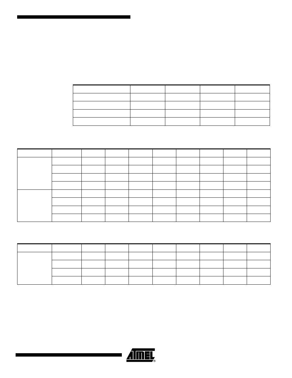
The RGB color space format is required for viewing images on a display screen preview, and the
YCbCr color space format is required for encoding.
All the sensors do not output the YCbCr or RGB components in the same order. The ISI allows
the user to program the same component order as the sensor, reducing software treatments to
restore the right format.
Table 45-2.
Data Ordering in YCbCr Mode
Mode
Byte 0
Byte 1
Byte 2
Byte 3
Default
Cb(i)
Y(i)
Cr(i)
Y(i+1)
Mode1
Cr(i)
Y(i)
Cb(i)
Y(i+1)
Mode2
Y(i)
Cb(i)
Y(i+1)
Cr(i)
Mode3
Y(i)
Cr(i)
Y(i+1)
Cb(i)
Table 45-3.
RGB Format in Default Mode, RGB_CFG = 00, No Swap
Mode
Byte
D7
D6
D5
D4
D3
D2
D1
D0
RGB 8:8:8
Byte 0
R7(i)
R6(i)
R5(i)
R4(i)
R3(i)
R2(i)
R1(i)
R0(i)
Byte 1
G7(i)
G6(i)
G5(i)
G4(i)
G3(i)
G2(i)
G1(i)
G0(i)
Byte 2
B7(i)
B6(i)
B5(i)
B4(i)
B3(i)
B2(i)
B1(i)
B0(i)
Byte 3
R7(i+1)
R6(i+1)
R5(i+1)
R4(i+1)
R3(i+1)
R2(i+1)
R1(i+1)
R0(i+1)
RGB 5:6:5
Byte 0
R4(i)
R3(i)
R2(i)
R1(i)
R0(i)
G5(i)
G4(i)
G3(i)
Byte 1
G2(i)
G1(i)
G0(i)
B4(i)
B3(i)
B2(i)
B1(i)
B0(i)
Byte 2
R4(i+1)
R3(i+1)
R2(i+1)
R1(i+1)
R0(i+1)
G5(i+1)
G4(i+1)
G3(i+1)
Byte 3
G2(i+1)
G1(i+1)
G0(i+1)
B4(i+1)
B3(i+1)
B2(i+1)
B1(i+1)
B0(i+1)
Table 45-4.
RGB Format, RGB_CFG = 10 (Mode 2), No Swap
Mode
Byte
D7
D6
D5
D4
D3
D2
D1
D0
RGB 5:6:5
Byte 0
G2(i)
G1(i)
G0(i)
R4(i)
R3(i)
R2(i)
R1(i)
R0(i)
Byte 1
B4(i)
B3(i)
B2(i)
B1(i)
B0(i)
G5(i)
G4(i)
G3(i)
Byte 2
G2(i+1)
G1(i+1)
G0(i+1)
R4(i+1)
R3(i+1)
R2(i+1)
R1(i+1)
R0(i+1)
Byte 3
B4(i+1)
B3(i+1)
B2(i+1)
B1(i+1)
B0(i+1)
G5(i+1)
G4(i+1)
G3(i+1)