Rainbow Electronics AT91CAP9S250A User Manual
Page 743
743
6264A–CAP–21-May-07
AT91CAP9S500A/AT91CAP9S250A
or
If the waveform is center aligned then the output waveform period depends on the counter
source clock and can be calculated:
By using the Master Clock (MCK) divided by an X given prescaler value
(with X being 1, 2, 4, 8, 16, 32, 64, 128, 256, 512, or 1024). The resulting period formula
will be:
By using a Master Clock divided by one of both DIVA or DIVB divider, the formula
becomes, respectively:
or
• the waveform duty cycle. This channel parameter is defined in the CDTY field of the
PWM_CDTYx register.
If the waveform is left aligned then:
If the waveform is center aligned, then:
• the waveform polarity. At the beginning of the period, the signal can be at high or low
level. This property is defined in the CPOL field of the PWM_CMRx register. By default the
signal starts by a low level.
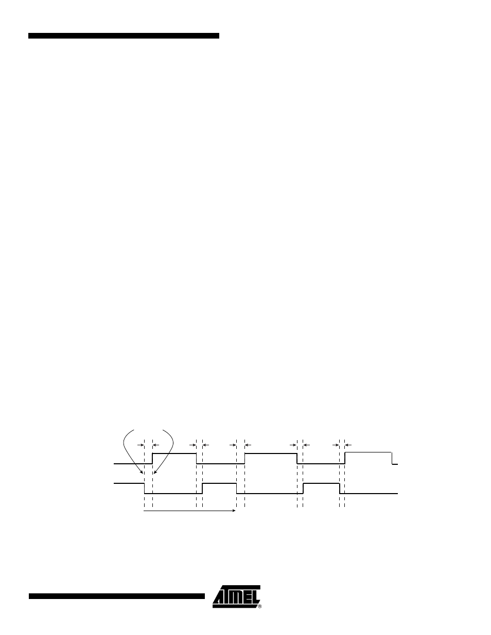
• the waveform alignment. The output waveform can be left or center aligned. Center
aligned waveforms can be used to generate non overlapped waveforms. This property is
defined in the CALG field of the PWM_CMRx register. The default mode is left aligned.
Figure 40-4. Non Overlapped Center Aligned Waveforms
Note:
1. See
for a detailed description of center aligned waveforms.
When center aligned, the internal channel counter increases up to CPRD and.decreases down
to 0. This ends the period.
CRPD
DIVA
×
(
)
MCK
-------------------------------------------
CRPD
DIVAB
×
(
)
MCK
-----------------------------------------------
2
X
CPRD
Ч
Ч
(
)
MCK
-------------------------------------------
2
CPRD
DIVA
Ч
Ч
(
)
MCK
------------------------------------------------------
2
CPRD
×
DIVB
×
(
)
MCK
------------------------------------------------------
duty cycle
period
1
fchannel_x_clock
CDTY
×
⁄
–
(
)
period
------------------------------------------------------------------------------------------------------------
=
duty cycle
period
2
⁄
(
)
1
fchannel_x_clock
CDTY
×
⁄
–
(
) )
period
2
⁄
(
)
------------------------------------------------------------------------------------------------------------------------------
=
PWM0
PWM1
Period
No overlap