4 ssc receive frame mode register – Rainbow Electronics AT91CAP9S250A User Manual
Page 599
599
6264A–CAP–21-May-07
AT91CAP9S500A/AT91CAP9S250A
36.8.4
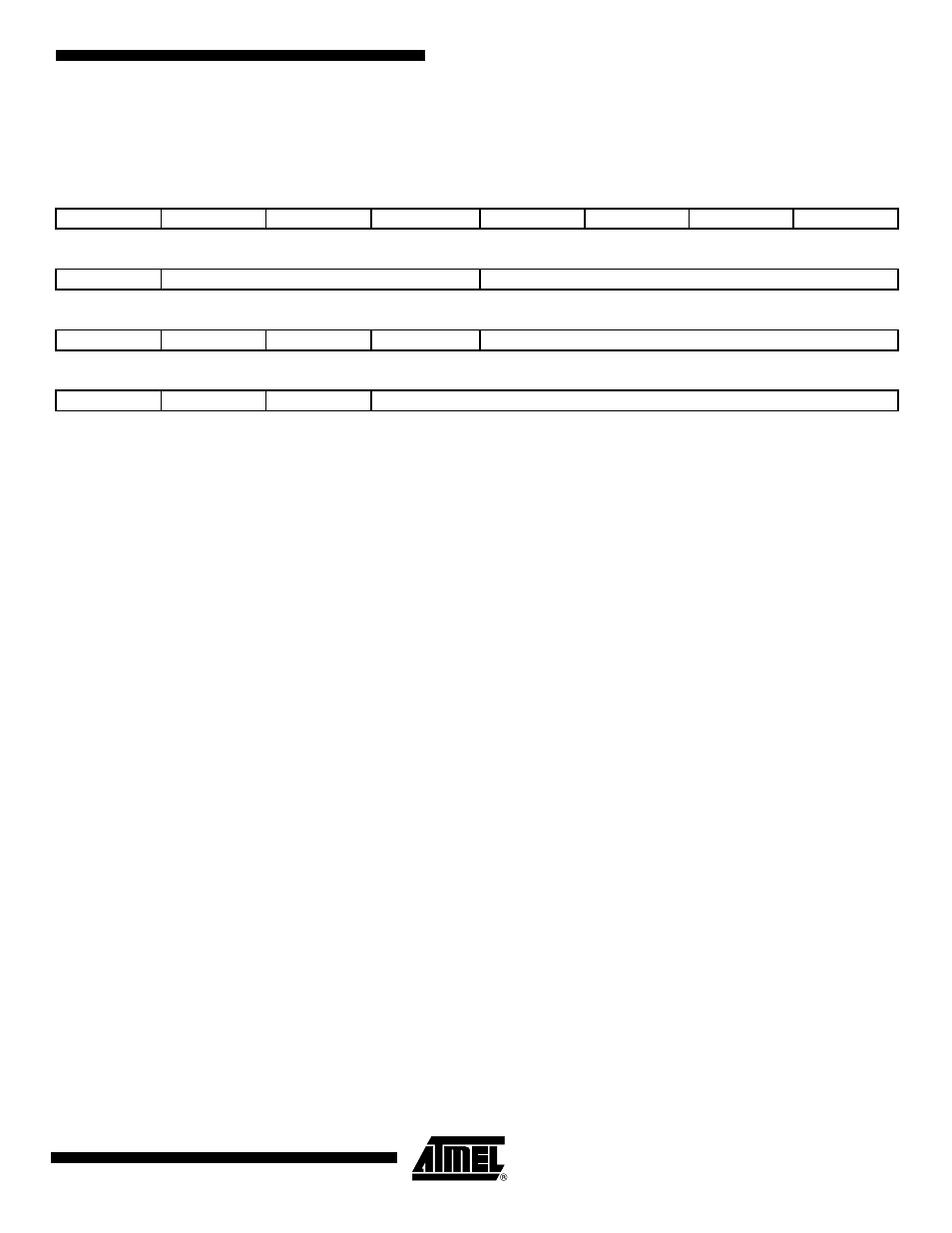
SSC Receive Frame Mode Register
Name:
SSC_RFMR
Access Type:
Read/Write
• DATLEN: Data Length
0: Forbidden value (1-bit data length not supported).
Any other value: The bit stream contains DATLEN + 1 data bits. Moreover, it defines the transfer size performed by the
PDC2 assigned to the Receiver. If DATLEN is lower or equal to 7, data transfers are in bytes. If DATLEN is between 8 and
15 (included), half-words are transferred, and for any other value, 32-bit words are transferred.
• LOOP: Loop Mode
0: Normal operating mode.
1: RD is driven by TD, RF is driven by TF and TK drives RK.
• MSBF: Most Significant Bit First
0: The lowest significant bit of the data register is sampled first in the bit stream.
1: The most significant bit of the data register is sampled first in the bit stream.
• DATNB: Data Number per Frame
This field defines the number of data words to be received after each transfer start, which is equal to (DATNB + 1).
• FSLEN: Receive Frame Sync Length
This field defines the number of bits sampled and stored in the Receive Sync Data Register. When this mode is selected by
the START field in the Receive Clock Mode Register, it also determines the length of the sampled data to be compared to
the Compare 0 or Compare 1 register.
This field is used with FSLEN_EXT to determine the pulse length of the Receive Frame Sync signal.
Pulse length is equal to FSLEN + (FSLEN_EXT * 16) + 1 Receive Clock periods.
31
30
29
28
27
26
25
24
–
–
–
–
–
–
–
FSEDGE
23
22
21
20
19
18
17
16
–
FSOS
FSLEN
15
14
13
12
11
10
9
8
–
–
–
–
DATNB
7
6
5
4
3
2
1
0
MSBF
–
LOOP
DATLEN