4 write mode – Rainbow Electronics AT91CAP9S250A User Manual
Page 182
182
6264A–CAP–21-May-07
AT91CAP9S500A/AT91CAP9S250A
22.8.4
Write Mode
The WRITE_MODE parameter in the SMC_MODE register of the corresponding chip select indi-
cates which signal controls the write operation.
22.8.4.1
Write is Controlled by NWE (WRITE_MODE = 1):
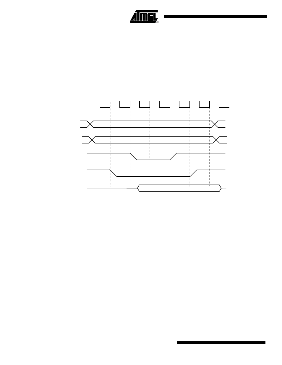
shows the waveforms of a write operation with WRITE_MODE set to 1. The data is
put on the bus during the pulse and hold steps of the NWE signal. The internal data buffers are
turned out after the NWE_SETUP time, and until the end of the write cycle, regardless of the
programmed waveform on NCS.
Figure 22-14. WRITE_MODE = 1. The write operation is controlled by NWE
22.8.4.2
Write is Controlled by NCS (WRITE_MODE = 0)
shows the waveforms of a write operation with WRITE_MODE set to 0. The data is
put on the bus during the pulse and hold steps of the NCS signal. The internal data buffers are
turned out after the NCS_WR_SETUP time, and until the end of the write cycle, regardless of
the programmed waveform on NWE.
MCK
D[31:0]
NCS
A
[25:2]
NBS0, NBS1,
NBS2, NBS3,
A0, A1
NWE,
NWR0, NWR1,
NWR2, NWR3